Apparatus for generating muons with intended use in a fusion reactor

a technology for generating muons and fusion reactors, which is applied in nuclear reactors, greenhouse gas reduction, nuclear engineering, etc., can solve the problems of high energy requirements, high cost, and inability to reliably and commercially viable fusion reactors using any of these techniques to be in operation

Inactive Publication Date: 2019-12-05
NORRONT FUSION ENERGY AS
View PDF0 Cites 2 Cited by
  • Summary
  • Abstract
  • Description
  • Claims
  • Application Information

AI Technical Summary

Benefits of technology

[0035]The hydrogen transfer catalyst may advantageously be porous, so that the hydrogen in the gaseous state can flow through the pores. This will provide for a large contact area between the hydrogen gas and the hydrogen transfer catalyst. At the same time, however, flow through the pores only will limit the attainable flow rate and thus possibly the rate of production of ultra-dense hydrogen.
[0036]The present inventor has found that flow through the pores o

Problems solved by technology

Both of these tracks involve difficult problems, and it is unlikely that reliable and commercially viable fusion reactors using any of these techniques will be in operation in the near future.
Existing methods of producing muons, for instance usi

Method used


Image

  • Apparatus for generating muons with intended use in a fusion reactor
  • Apparatus for generating muons with intended use in a fusion reactor
  • Apparatus for generating muons with intended use in a fusion reactor

Examples


Embodiment Construction

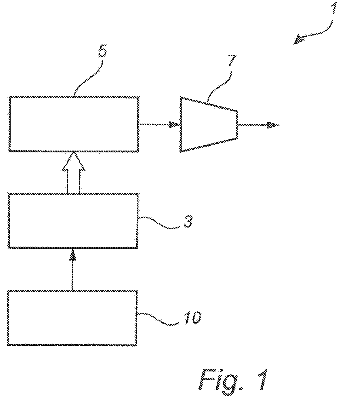
[0045]FIG. 1 is a schematic block diagram functionally illustrating a fusion reactor for muon catalyzed fusion using muon generator according to embodiments of the present invention.

[0046]The fusion reactor 1 comprises a muon generator 10, a vessel 3 containing hydrogen gas (which may, for example, be a suitable mix of protium, deuterium, and tritium), a vaporizer 5, and an electrical generator 7.

[0047]As is schematically shown in FIG. 1, muons generated by the muon generator 10 are used for catalyzing fusion according to, per se, known fusion reactions in the vessel 3. Heat resulting from the fusion reactions in the vessel 3 is used for vaporizing a process fluid, such as water, in the vaporizer. The resulting vapor-phase process fluid, such as steam, is used to drive the electrical generator 7, resulting in output of electrical energy. If only heat is needed, the electrical generator is not needed.

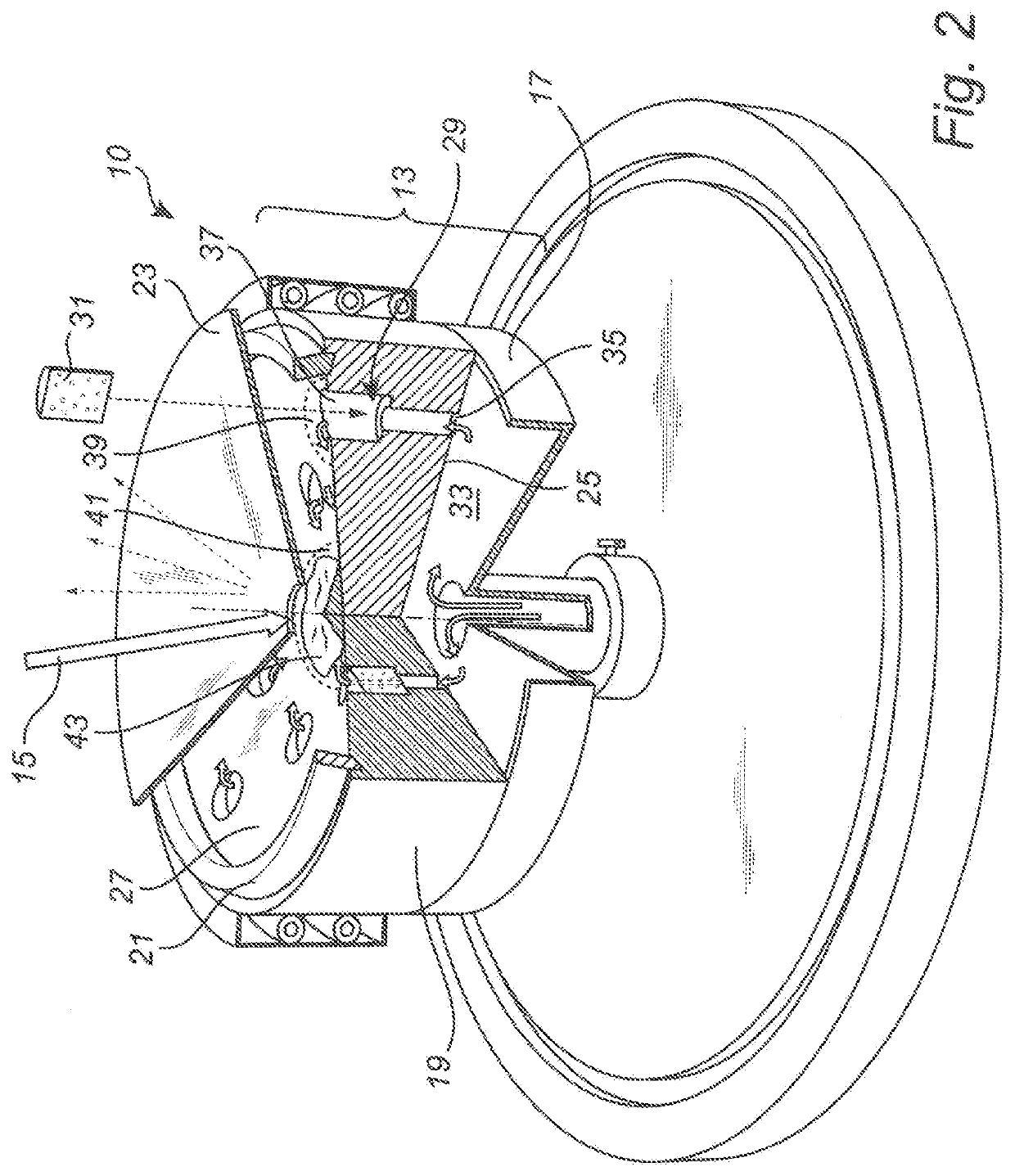
[0048]FIG. 2 is a schematic illustration of an example embodiment of the apparatus f...


PUM


Abstract

An apparatus for generating muons, comprising: a hydrogen accumulator including an inlet; an outlet separated from the inlet by a flow path; a hydrogen transfer catalyst arranged along the flow path; and an accumulating member for receiving hydrogen in ultra-dense state from the outlet at a receiving portion of the accumulating member and accumulating the hydrogen in the ultra-dense state at an accumulation portion of the accumulating member. The accumulating member has a downward sloping surface from the receiving portion to the accumulation portion. The apparatus further includes a field source, such as a laser, arranged to provide, to the accumulation portion of the accumulating member, a field adapted to stimulate emission of negative muons from hydrogen in the ultra-dense state. The apparatus further includes a specially designed barrier and a shield to retain the super-fluid ultra-dense hydrogen from creeping away from the accumulation portion of the generator.

Description

FIELD OF THE INVENTION[0001]The present invention relates to an apparatus for generating muons.BACKGROUND OF THE INVENTION[0002]Fusion is one of the candidates for future large scale generation of energy without the emission problems associated with burning fossil fuel and the fuel disposal problem of traditional fission nuclear power.[0003]Research into energy generation using fusion follows a number of parallel tracks. Most effort is currently spent on developing reactors for magnetic confinement fusion and inertial confinement fusion (ICF). Both of these tracks involve difficult problems, and it is unlikely that reliable and commercially viable fusion reactors using any of these techniques will be in operation in the near future.[0004]An alternative process known as muon-catalyzed fusion has been known since the 1950's, and was initially seen as promising. However, it was soon realized that each muon, even if it were absolutely stable, could only catalytically react about 100 to ...

Claims


Application Information

Patent Timeline
IPC IPC(8): G21B3/00
CPCG21B3/004G21B3/008G21B1/19Y02E30/10
Inventor HOLMLID, LEIF
Owner NORRONT FUSION ENERGY AS
Why Eureka
Try Eureka