Quick-change fused filament fabrication nozzle assembly

a technology of fused filament and assembly, which is applied in the direction of manufacturing tools, application layer means, other domestic objects, etc., can solve the problems of affecting the mechanical integrity of the nozzle exit aperture, affecting the operation of the fff extrusion system, and affecting the operation of the nozzle. the effect of reducing the nozzle size and the nozzle surfa

Active Publication Date: 2019-12-12
STRATSYS INC
View PDF0 Cites 3 Cited by
  • Summary
  • Abstract
  • Description
  • Claims
  • Application Information

AI Technical Summary

Benefits of technology

[0009]The present invention provides a system and method for quickly removing and installing a filament tube and nozzle in an FFF extrusion system. The system utilizes a primary manifold that includes a cooling block, a heating block and a quick-change mechanism. This primary manifold is adapted to mate a filament tube / nozzle assembly. The quick-change mechanism, which in a particular embodiment utilizes a recessed biased-bearing arrangement, enables the filament / nozzle assembly to be removed and inserted without the use of any tools, and without causing any significant downtime for the FFF extrusion system. Once removed, the filament tube / nozzle assembly can be refurbished by a technician, trained so as not to over torque the tube / nozzle threaded interface. This refurbishment (typically consisting of a cleaning and the installation of a new nozzle) could be accomplished “off-line”, without any impact on the continued use of FFF extrusion system.

Problems solved by technology

Not surprisingly, as the hot extrudate exits the nozzle it can abrade the interior nozzle surfaces.
The level of abrasion varies depending upon the chemical and mechanical properties of the particular extrudate being utilized, but over time the nozzle will invariably become worn.
This wear results in the loss of the mechanical integrity of the nozzle exit aperture 112 (typically a 0.2-0.5 mm bore) and can cause unwanted variability in extrudate consistency / diameter, as well as nozzle clogging.
In general, FFF nozzle replacement is time-consuming process that results in unwanted FFF system down-time and can expose the system's filament tube to excessive amounts of torque from manually wrenching the nozzle both out of and in to place.
Such torqueing can cause unwanted deformation of the filament tube and surrounding components.

Method used


Image

  • Quick-change fused filament fabrication nozzle assembly
  • Quick-change fused filament fabrication nozzle assembly
  • Quick-change fused filament fabrication nozzle assembly

Examples


Embodiment Construction

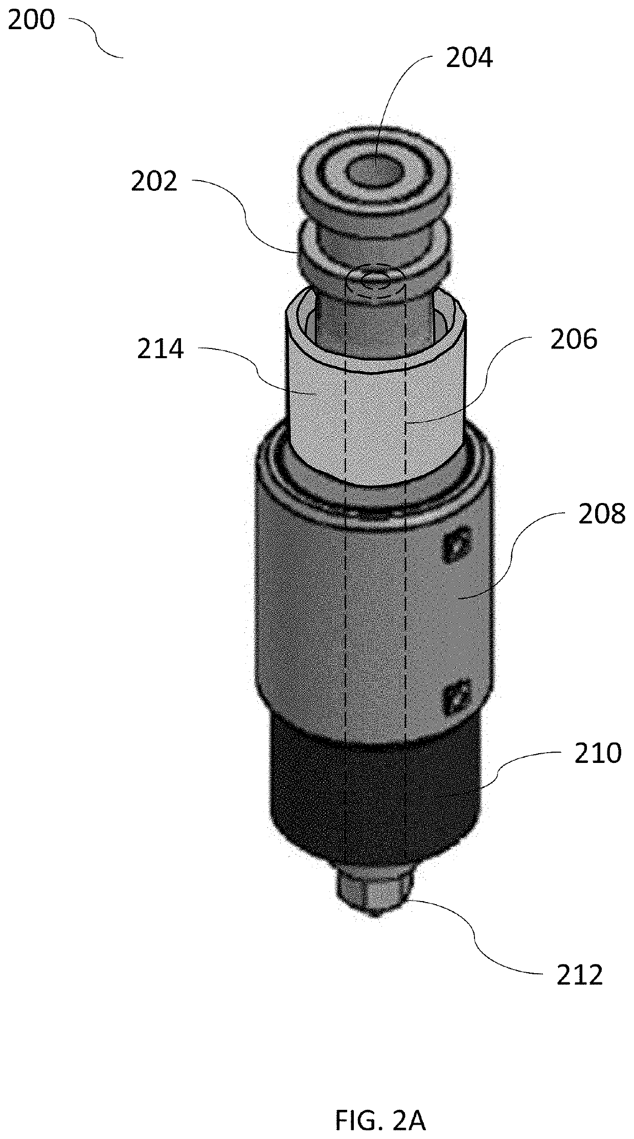
[0017]FIG. 2A a perspective view of an FFF extrusion assembly in accordance with a particular embodiment of the present disclosure. As illustrated, assembly 200 includes coupler 202, which facilitates attachment of the assembly to an FFF system and a supply of filament which is fed down orifice 204 and into the assembly's filament tube 206. Filament tube 206 (represented by the dashed lines) is internal to the extrusion assembly and positioned along the assembly's central axis. Cooling block 208 and heating block 210 are situated coaxially along the filament tube, and nozzle 212 is attached to lower end of filament tube 206. Quick-change mechanism 214 is shown to be coaxially situated above cooling block 208.

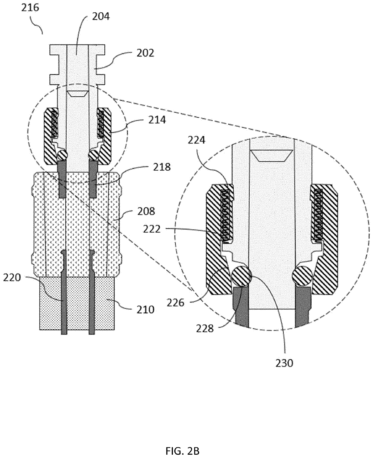
[0018]FIG. 2B provides a cross-sectional view of the primary manifold 216 of extrusion assembly 200. As shown, coupler 202 is connected to cooling block 208 by connecting ring 218, and cooler block 208 is connected to heating block 210 by connecting ring 220. Quick-change mechan...


PUM

PropertyMeasurementUnit
mechanicalaaaaaaaaaa
chemicalaaaaaaaaaa
temperatureaaaaaaaaaa

Abstract

The present invention provides a system and method for quickly removing and installing a filament tube and nozzle in an FFF extrusion system. The system utilizes a primary manifold that includes a cooling block, a heating block and a quick-change mechanism. This primary manifold is adapted to mate a filament tube/nozzle assembly. The quick-change mechanism, which in a particular embodiment utilizes a recessed biased-bearing arrangement, enables the filament/nozzle assembly to be removed and inserted without the use of any tools, and without causing any significant downtime for the FFF extrusion system. Once removed, the filament tube/nozzle assembly can be refurbished by a technician, trained so as not to over torque the tube/nozzle threaded interface. This refurbishment (typically consisting of a cleaning and the installation of a new nozzle) could be accomplished “off-line”, without any impact on the continued use of FFF extrusion system.

Description

FIELD OF THE INVENTION[0001]The present invention relates generally to fused filament fabrication, and more specifically to the filament tubes and extrusion nozzles employed in such fabrication systems and processes.BACKGROUND OF THE INVENTION[0002]The additive manufacturing process is widely known as “3D printing.” Numerous 3D-printing methodologies have been described in prior art, the most common being solid-laser sintering (SLS), stereolithography (SLA), and extrusion-based 3D printing or fused filament fabrication (FFF).[0003]All of these methods involve depositing a thin layer of thermoplastic or thermoset materials. In FFF, thin strands of material (referred to herein as “extrudate”) are deposited from a deposition nozzle onto a build surface. As the filament moves through the FFF system, it undergoes mechanical, chemical, and thermal changes. Deposition proceeds in a controlled pattern on the build surface to construct a 3D object.[0004]In operation of an FFF system, a filam...

Claims


Application Information

Patent Timeline
Patent Type & Authority Applications(United States)
IPC IPC(8): B29C47/08B29C64/209B29C64/118B29C47/00
CPCB29C64/209B29C64/118B33Y30/00B29L2031/731B29C48/2562B29C48/2566B29C48/2565B29C48/86B29C48/05B29C48/301B29C48/865B29C48/87B29C48/872B33Y40/00
Inventor ARMIJO, ARMANDO
Owner STRATSYS INC
Why Eureka
Try Eureka