Method and device for dynamic scheduling in ue and base station

a dynamic scheduling and transmission method technology, applied in the direction of wireless communication, signalling characterisation, error prevention/detection by transmission repeat, etc., can solve the problems of waste of control signaling resources, reduce the overhead of control signaling, improve transmission efficiency, and reduce complexity

Active Publication Date: 2019-12-12
SHANGHAI LANGBO COMM TECH CO LTD
View PDF0 Cites 3 Cited by
  • Summary
  • Abstract
  • Description
  • Claims
  • Application Information

AI Technical Summary

Benefits of technology

[0153]Compared with the prior art, the disclosure has the following technical advantages.
[0154]A payload size of the first signaling is adjusted based on a transmission mode, without the need to introduce a padding bit to keep the restriction that one format corresponds to one payload size; thus, ...

Problems solved by technology

If the DCI format is still designed according to the above approach that one DCI format corresponds to ...

Method used


Image

  • Method and device for dynamic scheduling in ue and base station
  • Method and device for dynamic scheduling in ue and base station
  • Method and device for dynamic scheduling in ue and base station

Examples


embodiment 1

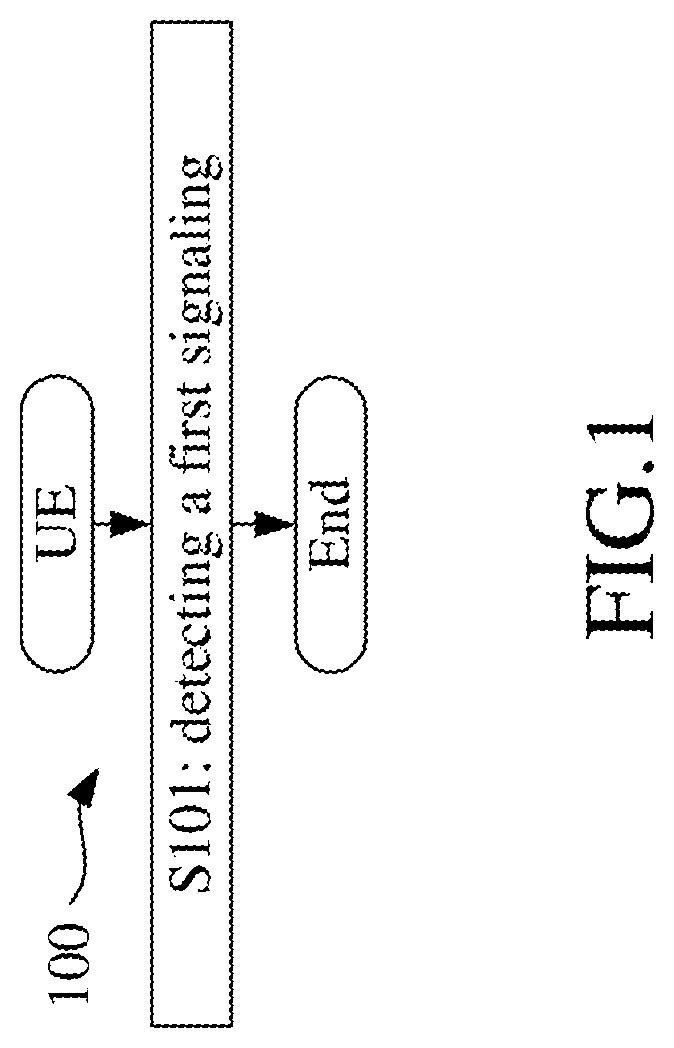
[0169]Embodiment 1 illustrates an example of a flowchart of processing of a UE, as shown in FIG. 1. In 100 shown in FIG. 1, each box represents one step. In Embodiment 1, the UE in the disclosure detects a first signaling in S101.

[0170]In Embodiment 1, the first signaling is a physical layer signaling; the first signaling includes a first bit block, and a number of bits in the first bit block is related to a transmission mode of the first signaling; the transmission mode of the first signaling is one of multiple candidate modes; the multiple candidate modes include at least a first candidate mode and a second candidate mode; for the first candidate mode, the first bit block is transmitted multiple times; and for the second candidate mode, the first bit block is transmitted once.

embodiment 2

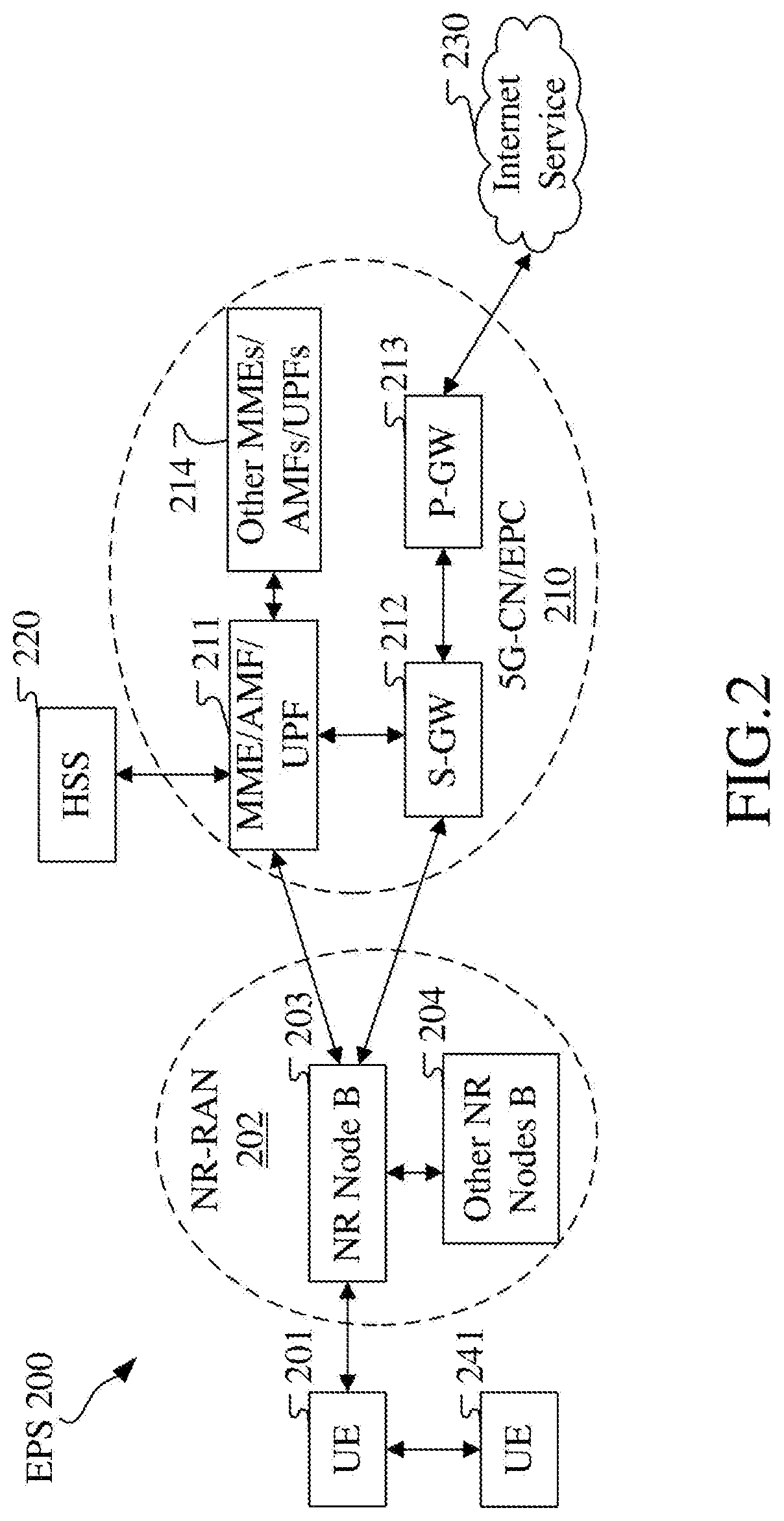
[0171]Embodiment 2 illustrates an example of a diagram of a network architecture, as shown in FIG. 2.

[0172]FIG. 2 is a diagram illustrating a network architecture 200 of NR 5G, LTE and Long-Term Evolution Advanced (LTE-A) systems. The NR 5G or LTE network architecture 200 may be called an Evolved Packet System (EPS) 200 or some other appropriate terms. The EPS 200 may include one or more UEs 201, a Next Generation-Radio Access Network (NG-RAN) 202, an Evolved Packet Core / 5G-Core Network (EPC / 5G-CN) 210, a Home Subscriber Server (HSS) 220 and an Internet service 230. The EPS may be interconnected with other access networks. For simple description, the entities / interfaces are not shown. As shown in FIG. 2, the EPS provides packet switching services. Those skilled in the art are easy to understand that various concepts presented throughout the disclosure can be extended to networks providing circuit switching services or other cellular networks. The NG-RAN includes an NR node B (gNB) 2...

embodiment 3

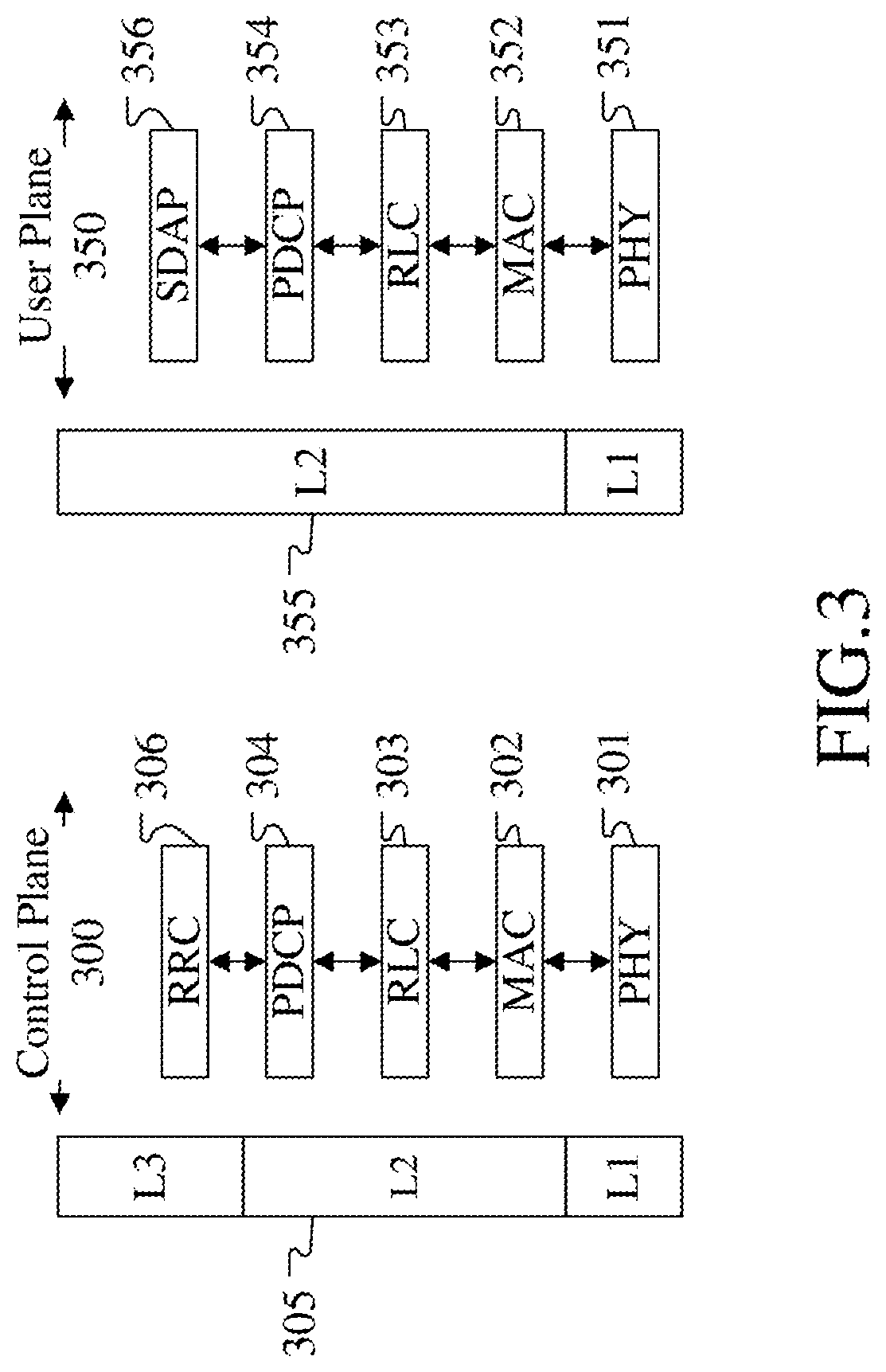
[0175]Embodiment 3 illustrates a diagram of an embodiment a radio protocol architecture of a user plane and a control plane according to the disclosure, as shown in FIG. 3. FIG. 3 is a diagram illustrating an embodiment of a radio protocol architecture of a user plane 350 and a control plane 300. In FIG. 3, the radio protocol architecture of a control plane 300 between a first communication node (UE, gNB or RSU in V2X) and a second communication node (gNB, UE or RSU in V2X) or between two UEs is illustrated by three layers, which are a Layer 1, a Layer 2 and a Layer 3 respectively. The Layer 1 (L1 layer) 301 is the lowest layer and implements various PHY (physical layer) signal processing functions. The L1 layer will be referred to herein as the PHY 301. The Layer 2 (L2 layer) 305 is above the PHY 301, and is responsible for the link between the first communication node and the second communication node and between two UEs over the PHY 301. The L2 layer 305 includes a Medium Access ...


PUM


Abstract

The disclosure provides a method and a device for dynamic scheduling in a User Equipment (UE) and a base station. The UE detects a first signaling. The first signaling is a physical layer signaling. The first signaling includes a first bit block, and a number of bits in the first bit block is related to a transmission mode of the first signaling. The transmission mode of the first signaling is one of multiple candidate modes. For the first candidate mode, the first bit block is transmitted multiple times; and for the second candidate mode, the first bit block is transmitted once. The disclosure establishes a relationship between a payload size of the first signaling and a transmission mode of the first signaling, thus reducing the payload size of the first signaling, simplifying the complexity of blind decoding of control signalings, and improving transmission efficiency and spectrum efficiency of the system.

Description

CROSS-REFERENCE TO RELATED APPLICATION[0001]This application is a continuation of International Application No. PCT / CN2017 / 074895, filed Feb. 25, 2017, the full disclosure of which is incorporated herein by reference.BACKGROUNDTechnical Field[0002]The disclosure relates to transmission methods and devices in wireless communication systems, and in particular to a transmission method and device of control channels in wireless communication for dynamic scheduling.Related Art[0003]In existing Long Term Evolution (LTE) systems, for a downlink subframe, a User Equipment (UE) will search for corresponding Downlink Control Information (DCI) in the downlink subframe. A downlink grant generally schedules a Downlink Shared Channel (DL-SCH) of a current subframe, while an uplink grant generally schedules an Uplink Shared Channel (UL-SCH) of a subsequent subframe. Different DCI formats correspond to different payload sizes, and different payload sizes correspond to independent blind decodings. I...

Claims


Application Information

Patent Timeline
IPC IPC(8): H04W72/12H04W72/04H04L1/18H04L1/00H04L5/00
CPCH04L5/0082H04W72/0446H04W72/0453H04W72/1257H04L1/0003H04L1/1819H04L1/0025H04L1/003H04L1/08H04W72/535
Inventor ZHANG, XIAOBO
Owner SHANGHAI LANGBO COMM TECH CO LTD
Why Eureka
Try Eureka