
System and method for positioning a surgical tool

a surgical tool and navigation system technology, applied in the field of surgical navigation system, can solve the problems of difficult direct visual control of the positioning of the surgical instrument used by the surgeon, high radiation dose for both the surgeon and the patient, and the cost of sophisticated navigation system, etc., and achieve the effect of convenient operation and more accurate surgical procedures

Pending Publication Date: 2019-12-19
WALDEMAR LINK GMBH & CO
View PDF1 Cites 6 Cited by
  • Summary
  • Abstract
  • Description
  • Claims
  • Application Information

AI Technical Summary

Benefits of technology

The patent text describes a surgical tool that can be locked in different positions for different procedures. The tool has a processor that detects the orientation of the tool, and can adjust the pitch angle (the angle at which the tool is positioned) to match a stored position. The user can also use a voice control to change the pitch angle by speaking a certain phrase. This allows for easier and more intuitive positioning of the tool during surgery.

Problems solved by technology

However, with minimally invasive surgery, direct visual control typically used for the positioning of instruments used by the surgeon is rather difficult.
However, such sophisticated navigation systems are expensive, complex to operate, and as a result sparingly used.
However, continued use of the C-arm device subjects both the surgeon and the patient to a high radiation dose due to repeated X-ray exposure.
Further, most C-arms have only one direction of view and consequently require intraoperative repositioning quite often, which can be detrimental to positional accuracy, unduly time consuming, and increases the risk of infection.
The result can be high radiation doses, frustration, and longer than desired surgery times.
This device generally improves a surgeons ability to determine positioning of the tool in an area with limited access, and consequently restricted visual observance.
However, it can be rather difficult for the surgeon to control the plurality of displays in order to check whether a desired orientation has already been reached or is maintained.

Method used


Image

  • System and method for positioning a surgical tool
  • System and method for positioning a surgical tool
  • System and method for positioning a surgical tool

Examples


Embodiment Construction

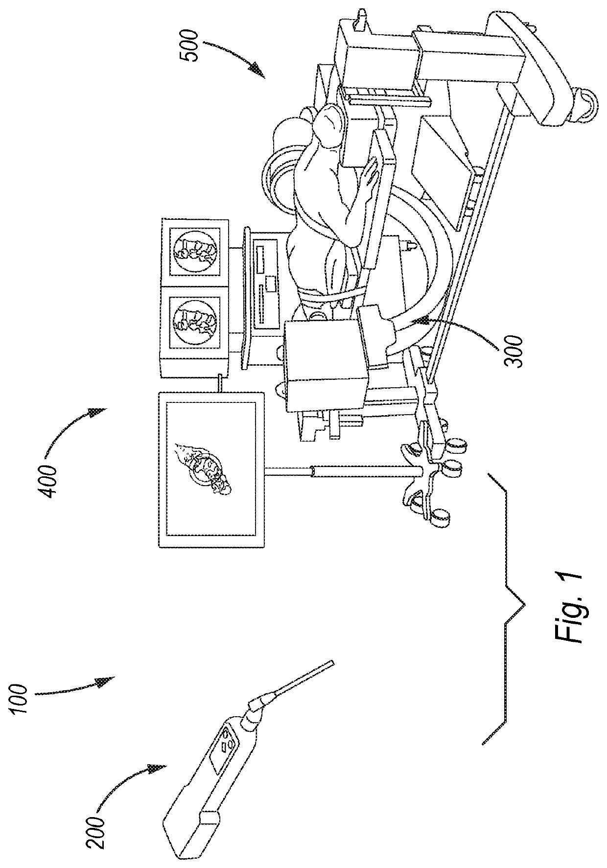
[0041]Detailed embodiments of the present surgical navigation system, and corresponding methods, are disclosed herein. However, it is to be understood that the disclosed embodiments are merely illustrative of a surgical navigation system, and of methods, that may be embodied in various forms. In addition, each of the examples given in connection with the various embodiments of the systems and methods are intended to be illustrative, and not restrictive. Further, the drawings and photographs are not necessarily to scale, and some features may be exaggerated to show details of particular components. In addition, any measurements, specifications, and the like shown in the figures are intended to be illustrative, and not restrictive. Therefore, specific structural and functional details disclosed herein are not to be interpreted as limiting, but merely as a representative basis for teaching one skilled in the art to variously employ the present system and methods.

[0042]With reference to...


PUM


Abstract

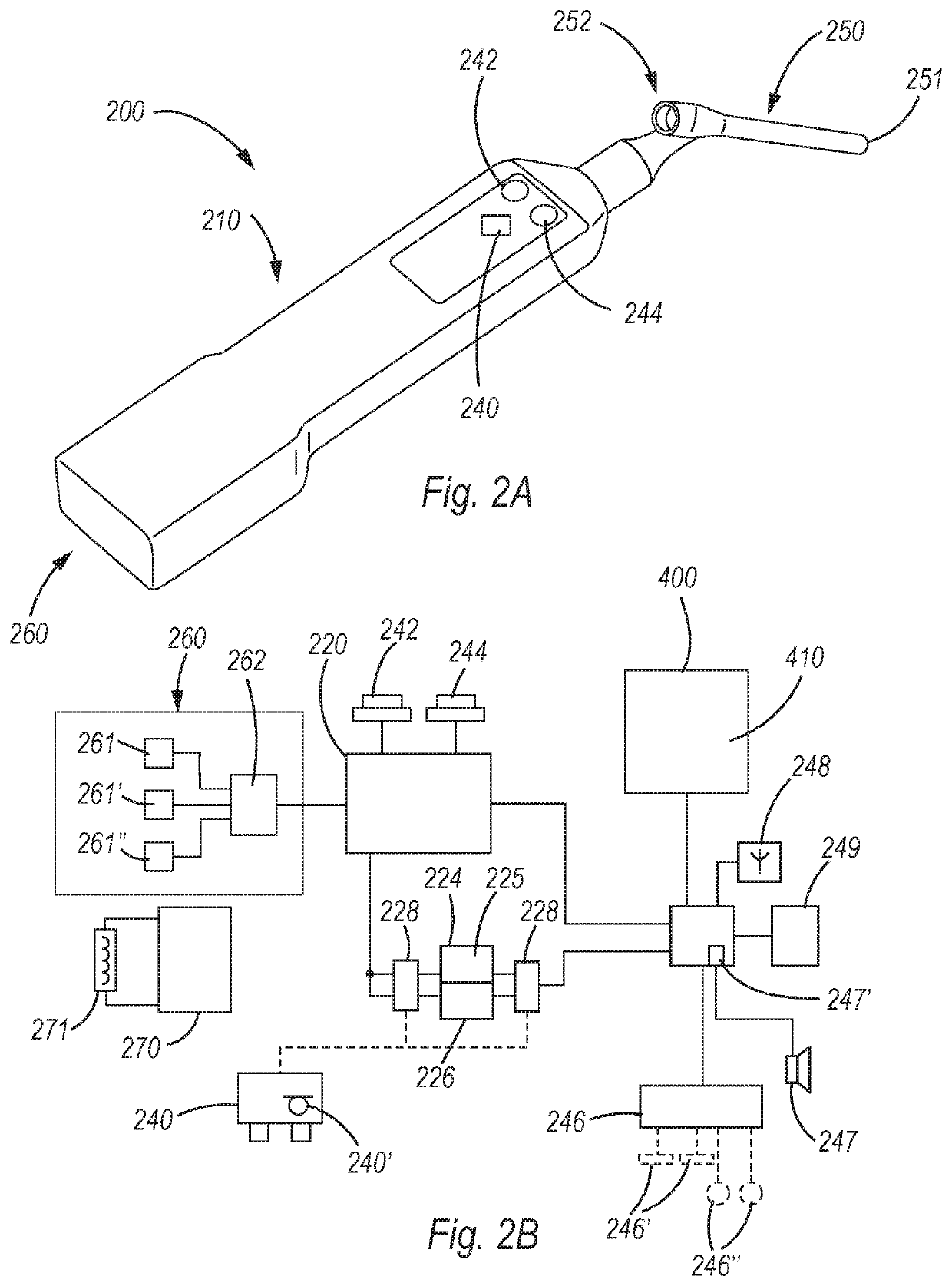
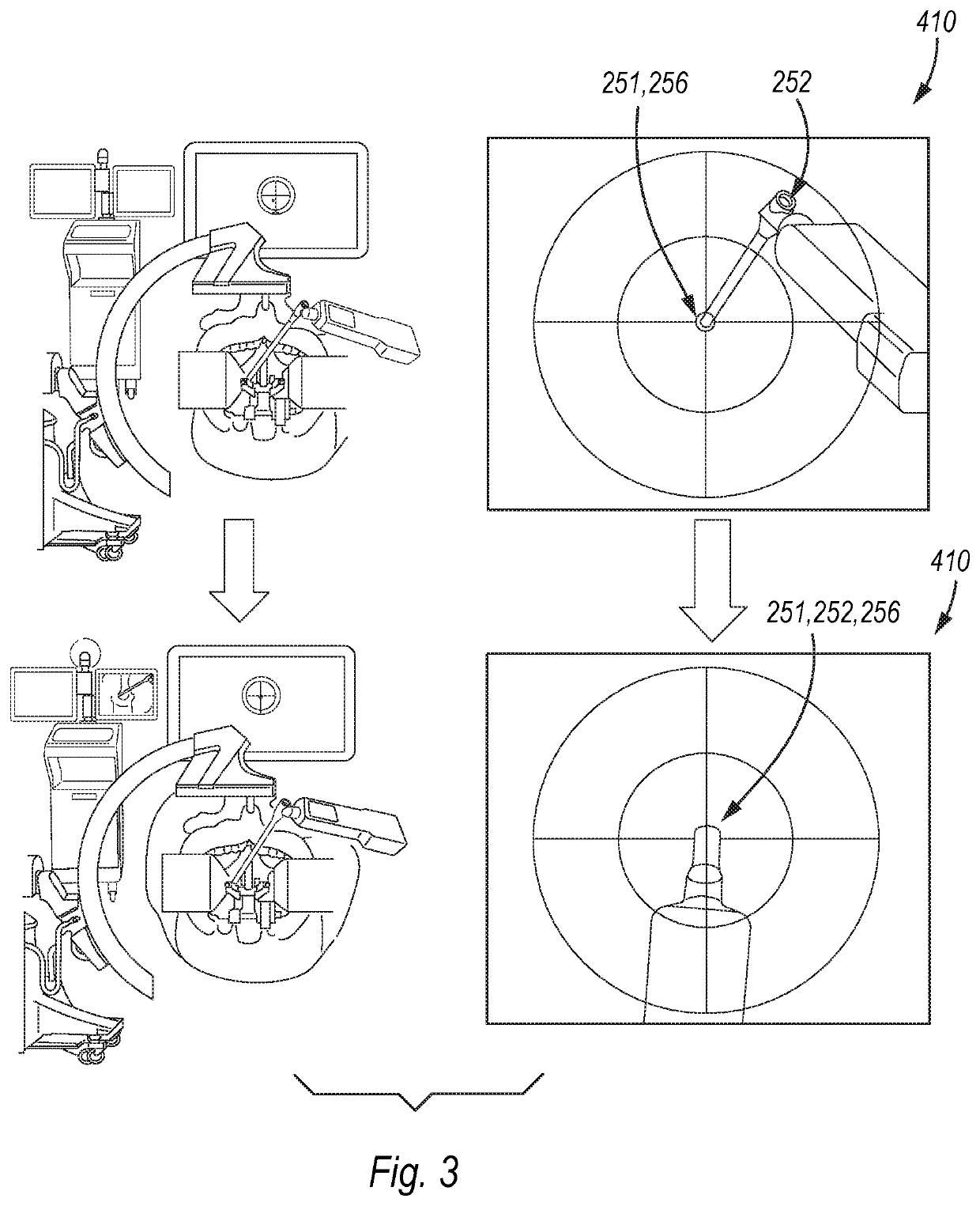
A surgical navigation system for providing computer-aided surgery. The surgical navigation system includes a handheld surgical tool with computer-aided navigation, an imaging device, an alignment module, and a user interface module. The handheld surgical tool includes at least one sensor for measuring a position of the tool in three dimensions, and at least one set key. A processor and at least one display device are associated with the handheld surgical tool and configured to display a target trajectory of the handheld surgical tool for the surgical procedure.

Description

CROSS-REFERENCE TO RELATED APPLICATION[0001]This Application claims priority to U.S. Provisional Patent Application No. 62 / 763,491, filed on Jun. 15, 2018, the entirety of which is incorporated herein by reference.FIELD OF THE INVENTION[0002]The invention relates to a surgical navigation system having a handheld surgical tool with computer-aided navigation. The handheld surgical tool comprises a housing, an instrument shaft and a sensor unit, the housing comprising at least one set key and a position memory configured to store a data set for a position upon activation of the at least one set key.BACKGROUND OF THE INVENTION[0003]Surgery is moving from “open” methodologies, which use direct vision for implant placement, to less invasive techniques, which rely upon fluoroscopic control or sophisticated navigation techniques to guide implantation. The increasing interest in these less invasive procedures has contributed to greater use of fluoro, or alternatively, large capital investmen...

Claims


Application Information

Patent Timeline
Patent Type & Authority Applications(United States)
IPC IPC(8): A61B34/20A61B34/00
CPCA61B2034/2048A61B34/20A61B2034/2065A61B34/25
Inventor LINK, HELMUT D.SIGNORETTI, RICCARDO
Owner WALDEMAR LINK GMBH & CO
Learn More