Preform and one-piece vane for turbomachine

a technology of one-piece vanes and fiber preforms, which is applied in the direction of machines/engines, efficient propulsion technologies, other domestic articles, etc., can solve the problems of limiting optimization, aerodynamic optimization, and in particular the optimization of the airfoil portion, so as to achieve good aerodynamic properties and improve mechanical strength

Active Publication Date: 2019-12-19
SN DETUDE & DE CONSTR DE MOTEURS DAVIATION S N E C M A
View PDF0 Cites 0 Cited by
  • Summary
  • Abstract
  • Description
  • Claims
  • Application Information

AI Technical Summary

Benefits of technology

[0037]In certain embodiments, at least one fiber strip is fitted to a transverse segment by being put against the bottom surface of said transverse segment. This configuration provides better mechanical strength to withstand the centrifugal forces that are applied to the platforms while the turbine engine is in operation.
[0038]In certain embodiments, the top surface of at least one fiber strip is flush with the top surface of at least one transverse segment. In this way, the top surface of the final platform is plane and regular, thereby providing good aerodynamic properties.

Problems solved by technology

Nevertheless, it is complicated to make a fiber preform with integrally incorporated platforms by 3D weaving.
Specifically, such a single-piece configuration involves causing large yarn layers to exit during the weaving in order to form the platforms, including in zones where it would nevertheless be desirable to conserve considerable thickness: thus, weaving the platforms simultaneously leads to shape and design constraints on the airfoil portion, thereby limiting optimization, and in particular aerodynamic optimization, of the airfoil portion.

Method used


Image

  • Preform and one-piece vane for turbomachine
  • Preform and one-piece vane for turbomachine
  • Preform and one-piece vane for turbomachine

Examples


Embodiment Construction

[0060]In order to make the invention more concrete, an embodiment is described below in detail with reference to the accompanying drawings. It should be recalled that the invention is not limited to this embodiment.

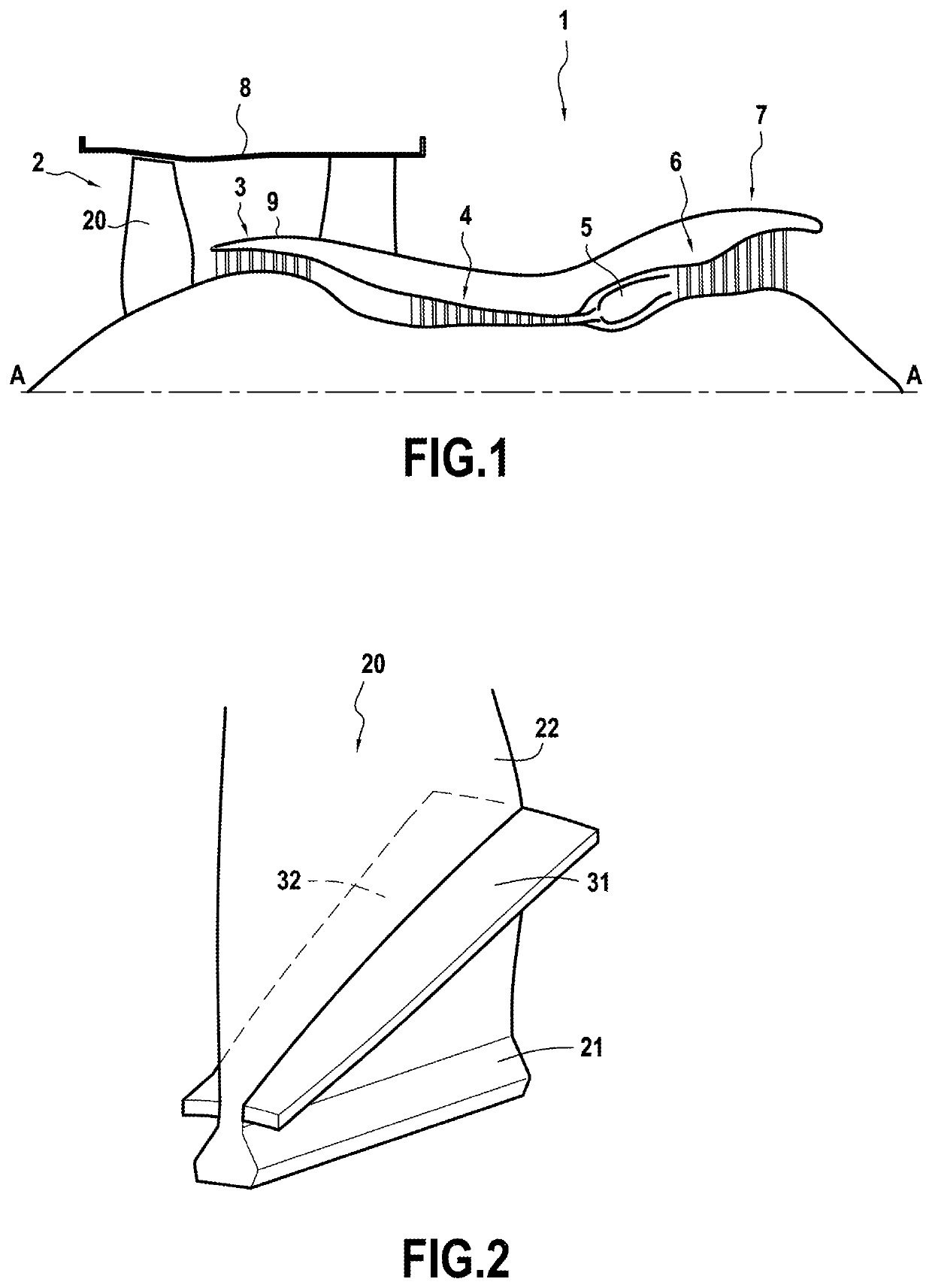
[0061]FIG. 1 is a view of a bypass turbojet 1 in accordance with the disclosure and shown in section on a vertical plane containing its main axis A. From upstream to downstream in the flow direction of the air stream, it comprises a fan 2, a low pressure compressor 3, a high pressure compressor 4, a combustion chamber 5, a high pressure turbine 6, and a low pressure turbine 7. In its upstream portion, the turbojet 1 has an outer casing 8 and an inner casing 9 defining two concentric flow passages, namely a primary passage I and a secondary passage II.

[0062]FIG. 2 is a diagrammatic perspective view of a blade 20 of the fan 2. Such a blade 20 comprises a blade root 21 and an airfoil portion 22. The airfoil portion 22 serves mainly to perform the aerodynamic function of the ...


PUM

PropertyMeasurementUnit
structureaaaaaaaaaa
lengthaaaaaaaaaa
widthaaaaaaaaaa

Abstract

A fiber preform for a turbine engine blade, the preform comprising a main fiber structure (40) obtained by a single piece of three-dimensional weaving, said main first structure (40) comprising a first longitudinal segment (41) suitable for forming a blade root, a second longitudinal segment (42) extending the first longitudinal segment (41) and suitable for forming an airfoil portion (22), and a first transverse segment (51) extending transversely from the junction (49) between the first and second longitudinal segments (41, 42) and suitable for forming a first tongue for a first platform, wherein the first transverse segment (51) extends axially over a length that is less than 30%, preferably less than 15%, of the length of the junction (49) between the first and second longitudinal segments (41, 42).

Description

FIELD OF THE INVENTION[0001]The present disclosure relates to a fiber preform for a turbine engine blade and also to a single-piece blade made by means of such a preform, to a fan, and to a turbine engine including such a blade.[0002]Such a preform may be used for making a single-piece blade that includes aerodynamic platforms. Such blades may in particular be fan blades for an airplane turbojet, for example.STATE OF THE PRIOR ART[0003]A conventional bypass turbojet has a fan from which the stream is split into a primary stream that is directed to the compressors, the combustion chamber, and then the turbines of the engine, and a bypass secondary stream that delivers the major part of the thrust.[0004]In order to reduce the weight of turbojets and reduce the number of parts making them up, proposals have been made, in particular in international application WO 2013 / 104852, to use three-dimensional (3D) weaving to make composite material fan blades with integrally incorporated platfo...

Claims


Application Information

Patent Timeline
Patent Type & Authority Applications(United States)
IPC IPC(8): B29B11/16B29C70/22
CPCB29C70/222F01D5/282F05D2300/6012B29D99/0025B29B11/16F05D2300/603Y02T50/60B29L2031/08
Inventor GUIVARC'H, JÉRÉMYBOISSON, ALEXANDRE BERNARD MARIEDE GAILLARD, THOMAS ALAINNOTARIANNI, GILLES PIERRE-MARIE
Owner SN DETUDE & DE CONSTR DE MOTEURS DAVIATION S N E C M A
Why Eureka
Try Eureka