Method for manufacturing a rear section of an aircraft and aircraft rear section manufactured by said method

a technology for aircraft and rear sections, which is applied in the direction of fuselages, fuselage bulkheads, transportation and packaging, etc., can solve the problems of significant aerodynamic drag penalty, high load, and reinforcements that add weight to the interface fittings and surrounding elements of the tail cone section, so as to reduce the lead time, reduce the effect of assembly and reduced fairings

Active Publication Date: 2019-12-19
AIRBUS OPERATIONS SL
View PDF0 Cites 1 Cited by
  • Summary
  • Abstract
  • Description
  • Claims
  • Application Information

AI Technical Summary

Benefits of technology

[0031]It permits a shielding manufacturing and assembly simplification because of less elements and riveted interfaces in continuous skin concept.
[0032]An advantage of the method is to remove or simplify an assembly between two major components typically performed in the last stages of the A / C assembly. At this stage since all parts are produced the capital immobilized is large and any lead time reduction is an important cost saving.
[0033]Fairings can be a problem for acoustic fatigue, vibration and debris release in case of engine debris impact. The present invention eliminates this problem because these fairings are reduced.
[0034]The continuous skin reduces the punctual load transmitted to the frame. This allows to reduce dimensions constraints on the frames due to the integration of such fittings. As a result, optimization of the frame height and thickness is possible, resulting on a weight reduction.

Problems solved by technology

The high loads requires to significant reinforcements, and the reinforcements add weight to the interface fittings and surrounding elements of the tail cone section.
Additionally, the interface fittings need to be covered by aerodynamic fairing that produces significant penalty of aerodynamic drag.
In addition, the assembly of these components is time consuming.

Method used


Image

  • Method for manufacturing a rear section of an aircraft and aircraft rear section manufactured by said method
  • Method for manufacturing a rear section of an aircraft and aircraft rear section manufactured by said method
  • Method for manufacturing a rear section of an aircraft and aircraft rear section manufactured by said method

Examples


Embodiment Construction

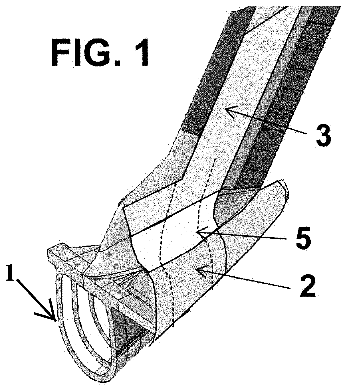
[0039]FIG. 1 is a perspective view of the aircraft rear section according to the present invention, manufactured with the method described previously.

[0040]As shown in this figure, this aircraft rear section comprises a tail cone 2 (made from tail cone sections) and a vertical tail plane 3 (made from vertical tail plane sections), and an external continuous skin 5, which may be made from a thermoplastic material, that joins the tail cone 2 and the vertical tail plane 3.

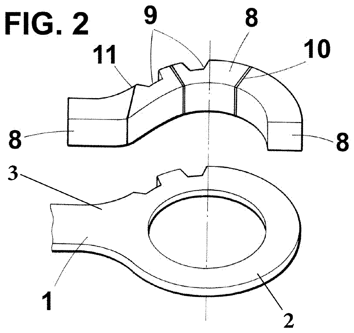
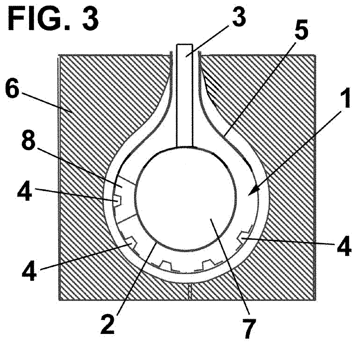
[0041]As shown in FIG. 2, a set of internal modular molds 8 are provided, on which pressure is applied by the expandable chamber 7. Compaction is provided to the external skin 5 between these internal molds 8 and the mold 6, which is external.

[0042]The modular molds 8 are used for positioning the pre-cured frames 1 between the modular molds 8.

[0043]As shown in this FIG. 2, there are a plurality of cut-outs 9 in the pre-cured frame 1 and in at least one modular mold 8 for placing the pre-cured stringers 4, and a joint ...


PUM

PropertyMeasurementUnit
internal pressureaaaaaaaaaa
perimeteraaaaaaaaaa
perimetersaaaaaaaaaa

Abstract

A method for manufacturing an aircraft rear section including a tail cone and a vertical tail plane, the method includes: providing pre-cured frames (1) each of which includes a section of the tail cone (2) and a section of the vertical tail plane (3); providing pre-cured stringers (4); placing the pre-cured stringers (4) each in respective positions within the pre-cured frames (1); placing a skin (5) around an external surface of the pre-cured frames (1); and curing the pre-cured frames (1), the pre-cured stringers (4), and the skin (5), forming the final aircraft rear section.

Description

RELATED APPLICATION[0001]This application claims priority to European Patent Application 18382441-6, filed Jun. 19, 2018, the entirety of which is incorporated by reference.FIELD OF THE INVENTION[0002]The present invention refers to a method for manufacturing a rear section of an aircraft, particularly for manufacturing the tail cone and the vertical tail plane of an aircraft at the same time. The present invention also refers to the aircraft rear section manufactured by said method.BACKGROUND OF THE INVENTION[0003]Conventionally, to build an aircraft fuselage, a series of frames in the shape of the fuselage cross sections are held in position on a rigid fixture. These frames are then joined with the fuselage skin panels that includes lightweight longitudinal elements called stringers that increase the buckling resistance of the skin. The stringers are attached to the skin by means of riveting, by cured resin or by bonding with special adhesives. The junction of the skin panels and ...

Claims


Application Information

Patent Timeline
Patent Type & Authority Applications(United States)
IPC IPC(8): B64F5/10B64C5/02B64C1/06B64C1/12
CPCB64C5/02B64C1/061B64C1/064B64F5/10B64C1/12B64C1/0685B64C2001/0072B29C33/505B29C44/12
Inventor MARTINO-GONZALEZ, ESTEBANARANA HIDALGO, ALBERTOSANCHEZ PEREZ, MELANIAGARCIA NIETO, CARLOSVAZQUEZ CASTRO, JESUS JAVIERMENARD, EDOUARDINIESTA LOZANO, FERNANDOCANAS RIOS, MARIA ALMUDENA
Owner AIRBUS OPERATIONS SL
Why Eureka
Try Eureka