Temperature calibrator

a calibrator and temperature technology, applied in the field of temperature calibrators, can solve the problems of wasting unnecessary energy, complex and the likelihood of failures to increase, and disadvantageous effect of efficiency both during cooling and heating, and achieve the effect of increasing efficiency in the heating-up phas

Active Publication Date: 2019-12-19
SIKA DR SIEBERT & KÜHN GMBH & CO KG
View PDF0 Cites 3 Cited by
  • Summary
  • Abstract
  • Description
  • Claims
  • Application Information

AI Technical Summary

Benefits of technology

[0006]It is now the underlying object of the disclosure to provide a remedy here; the efficiency in the heating-up phase should in particular be increased.

Problems solved by technology

To this extent, not only the time of the heating-up phase up to the reaching of the desired temperature is extended, but also unnecessary energy is rather furthermore wasted.
It is known in this connection also to use an adjustable shield instead of an air-permeable heat protection plate having small bores, with additional control and regulation hardware, however, being required to control the shield, which causes the complexity and the likelihood of failures to increase.
The use of an air-permeable heat protection plate is ultimately a compromise between air permeability and heat shielding and to this extent has a disadvantageous effect on efficiency both during cooling and during heating.

Method used


Image

  • Temperature calibrator
  • Temperature calibrator

Examples


Embodiment Construction

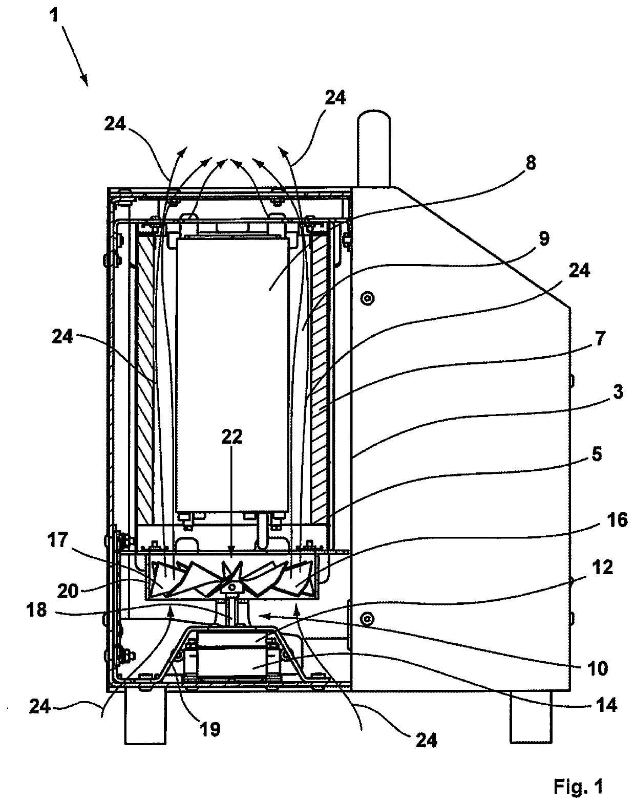
[0020]The temperature calibrator designed as a whole by 1 comprises the outer metal housing 3 and, spaced apart therefrom, the inner metal housing 5. The calibrator block 8 is located radially spaced apart from the inner metal housing 5 while forming a sleeve-like flow space 9. The inner metal housing 5 has an insulation 7 on the side facing the calibrator block 8 to prevent the outer metal housing from becoming too hot to avoid burns to the operators on it where possible. In the installed state below the calibrator block 8, the fan marked by 10 is located, with the fan marked by 10 having a motor 12 and a motor fan 14 for cooling the motor 12 that is located below the motor 12. The fan wheel 16 that is arranged in a so-called annular housing 20 is driven by the motor 12. The motor 12 is connected to the fan wheel 16 by the motor shaft 16. The motor shaft 18 is selected as comparatively long, with the length of the shaft 18 being in relation to the temperature that the motor is able...


PUM

PropertyMeasurementUnit
temperaturesaaaaaaaaaa
temperatureaaaaaaaaaa

Abstract

A temperature calibrator for calibrating temperature function devices has an outer and an inner housing as well as a calibrator block. The calibrator block is radially spaced from the inner housing to form a flow space. The flow space is in communication with the environment at the upper end and at the lower end to generate a flow. A fan having a fan wheel that can be driven by a motor is connected to the flow space. The fan wheel is formed from a heat-resistant material; and the fan forms a predominantly closed surface in a plan view.

Description

CROSS-REFERENCE TO RELATED APPLICATION[0001]This application claims priority of German Patent Application DE 10 2018 114 615.9 filed Jun. 19, 2018.FIELD OF THE INVENTION[0002]The present disclosure relates to a temperature calibrator for calibrating temperature function devices comprising an outer housing and an inner housing as well as a calibrator block, wherein the calibrator block has a radial spacing from the inner housing to form a flow space, with the flow space being in communication with the environment at the upper end and at the lower end to generate a flow, and with a fan having a fan wheel that can be driven by a motor being connected to the flow space.BACKGROUND OF THE INVENTION[0003]Temperature calibrators are sufficiently known. They typically serve the calibration of temperature function devices such as thermometers or also thermal switches.[0004]The object of a calibrator comprises heating or cooling to a temperature specified by the user for a thermometer or also ...

Claims


Application Information

Patent Timeline
Patent Type & Authority Applications(United States)
IPC IPC(8): G01K15/00H02K5/04H05K7/20
CPCG01K15/002H02K5/04G01K15/005H05K7/20H02K7/14F04D19/002F04D29/181
Inventor REHM-GUMBEL, MICHAEL
Owner SIKA DR SIEBERT & KÜHN GMBH & CO KG
Why Eureka
Try Eureka