Method for detecting and lessening fuel starvation in fuel cell systems

a fuel cell and operating system technology, applied in the field of fuel cell system operation, can solve the problems of weak cells, cell cannot deliver the same amount of current as its peers, and the possibility of voltage reversals in one or more cells, and achieve the effect of increasing the performance of the fuel cell stack

Active Publication Date: 2019-12-19
CELLCENTRIC GMBH & CO KG +1
View PDF0 Cites 3 Cited by
  • Summary
  • Abstract
  • Description
  • Claims
  • Application Information

AI Technical Summary

Benefits of technology

[0012]Fuel cell systems typically have a regulating apparatus for regulating the pressure of the fuel supplied to the fuel cell stack in the system. In systems where the outlet pressure from the regulating apparatus oscillates during operation (e.g. systems equipped with a fuel recirculation loop and a regulating apparatus comprising a jet pump in the loop), the performance of the fuel cell stack will also oscillate to a certain extent as a result of the periodic increase in fuel pressure provided to the anodes in the fuel cell stack. It was noticed however that the amplitude of these oscillations in stack performanc...

Problems solved by technology

A potential issue with a series stack of electrochemical cells of any kind is the possibility for having voltage reversals occur in one or more cells in the stack.
This can happen when, for some reason, an affected cell becomes incapable of delivering the same amount of current as its peers in the stack.
This can cause damage to the weak cell, thereby weakening it even further.
In fuel cells, fuel starvation is a well known condition that can weaken a cell and lead to voltage reversal situations.
Fuel starvation can arise for various reasons.
For instance, after storage in below freezing conditions, ice may form in the flow fields of the fuel cells and block the flow of fuel in or to the anode in a cell in the stack.
The now inadequate supply of fuel in that cell results in a fuel starvation condition.
The affected ce...

Method used


Image

  • Method for detecting and lessening fuel starvation in fuel cell systems
  • Method for detecting and lessening fuel starvation in fuel cell systems
  • Method for detecting and lessening fuel starvation in fuel cell systems

Examples


examples

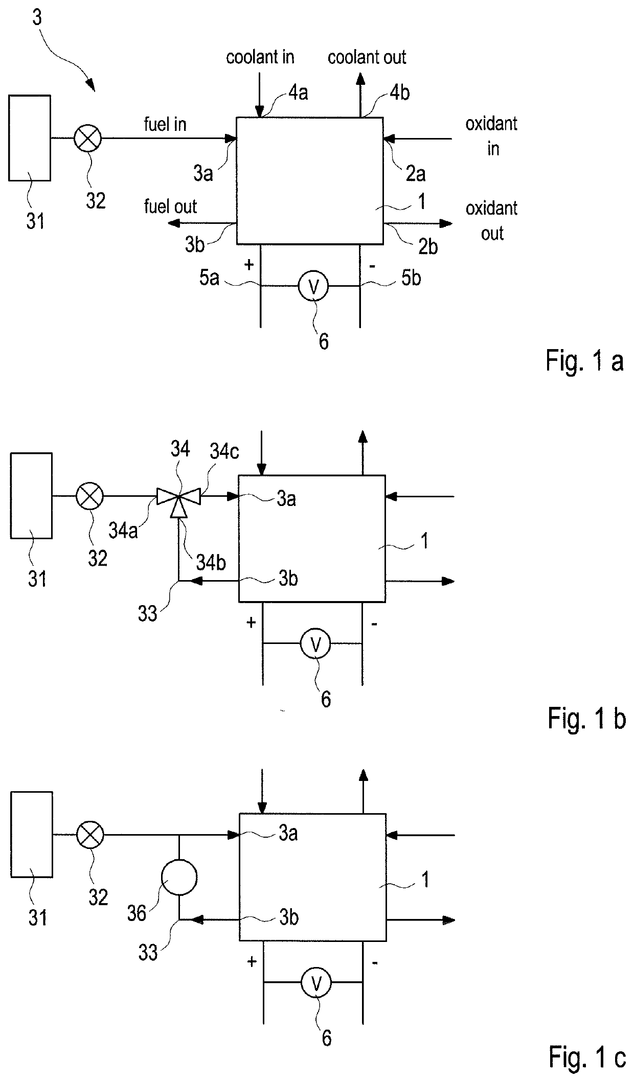
[0047]In the following tests, a fuel cell system comprising a solid polymer electrolyte fuel cell stack and suitable for use in automotive applications was employed. The system employed a recirculation line for recirculating anode exhaust back to the anode inlet. A jet pump was employed in the recirculation line as generally shown in the schematic of FIG. 1b.

[0048]The reactants supplied to the stack were hydrogen and air and the stack was operated under conditions typical of automotive applications. In particular, fresh fuel was supplied to the stack via an on-off type of regulating apparatus. This resulted in cycling of the jet pump output pressure and hence cycling of the anode inlet pressure.

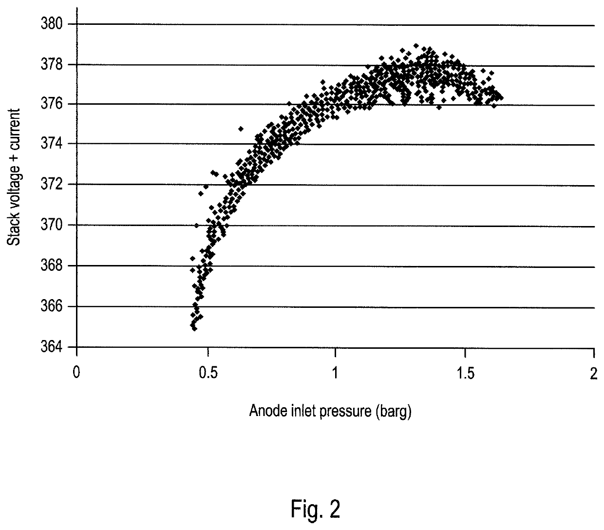
[0049]FIG. 2 illustrates the sensitivity of stack voltage to the pressure of the fuel supplied to the anode inlet of the stack. In FIG. 2, the stack voltage and pressure at the anode inlet were logged at a 1 Hz frequency while the stack was operated with the jet pump cycling. The [H2] at the...


PUM


Abstract

Methods are disclosed for detecting and lessening fuel starvation conditions in an operating fuel cell system. The fuel cell systems comprise a solid polymer electrolyte fuel cell with a regulating apparatus for regulating the pressure of fuel supplied to the anode inlet of the fuel cell, in which the outlet pressure from the regulating apparatus oscillates during operation. The methods involve monitoring an electrical output of the fuel cell during operation, determining the amplitude of oscillation in the electrical output, and then, if the determined amplitude of oscillation in the electrical output exceeds a predetermined amount thereby indicating a fuel starvation condition, taking a remedial action to lessen the fuel starvation condition.

Description

BACKGROUNDField of the Invention[0001]This invention relates to methods for detecting and lessening fuel starvation conditions in an operating fuel cell system. In particular, it relates to fuel cell systems comprising a solid polymer electrolyte fuel cell with regulating apparatus for regulating the pressure of fuel supplied to the anode inlet, in which the outlet pressure from the regulating apparatus oscillates when the fuel cell system is operating.Description of the Related Art[0002]Fuel cells such as solid polymer electrolyte (or proton exchange membrane) fuel cells electrochemically convert fuel and oxidant reactants (such as hydrogen and oxygen or air respectively) to generate electric power. Solid polymer electrolyte fuel cells employ a proton conducting, solid polymer membrane electrolyte between cathode and anode electrodes. A structure comprising a solid polymer membrane electrolyte sandwiched between these two electrodes is known as a membrane electrode assembly (MEA). ...

Claims


Application Information

Patent Timeline
IPC IPC(8): H01M8/04746H01M8/04089H01M8/04223H01M8/04537H01M8/10H01M8/04701H01M8/04828H01M8/04082
CPCH01M8/04201H01M8/04589H01M8/04097H01M8/04559H01M8/04231H01M2008/1095H01M8/04835H01M8/04723H01M8/04753H01M2250/20H01M8/10H01M8/0491H01M8/04679Y02T90/40Y02E60/50
Inventor FELLOWS, RICHARD
Owner CELLCENTRIC GMBH & CO KG
Why Eureka
Try Eureka