Refrigeration apparatus

a refrigerant and circuit technology, applied in mechanical apparatus, refrigeration components, light and heating apparatus, etc., can solve problems such as refrigerant leakage from refrigerant circuit, and achieve the effect of reliably ensuring safety, reducing the cost of repair work, and ensuring safety upon occurren

Active Publication Date: 2019-12-26
DAIKIN IND LTD
View PDF0 Cites 10 Cited by
  • Summary
  • Abstract
  • Description
  • Claims
  • Application Information

AI Technical Summary

Benefits of technology

[0047]Upon occurrence of erroneous detection by the refrigerant leak detection unit, this configuration suppresses occurrence of a situation in which the control unit performs the second control to release the refrigerant from the refrigerant circuit. This configuration therefore suppresses an increase in cost for repair work or corrective maintenance in relation to unnecessary release of the refrigerant from the refrigerant circuit by the second control.
[0048]A sixteenth aspect of the present disclosure provides the refrigeration apparatus according to any of the first to fifteenth aspects, wherein the refrigerant circuit includes a plurality of the usage-side circuits. The refrigerant release mechanism and a plurality of the first control valves are disposed upstream of each usage-side circuit with regard to the flow of the refrigerant. This configuration therefore sore reliably ensures the safety even when the refrigerant circuit includes the plurality of usage-side circuits.
[0049]Specifically, the refrigerant circuit including a plurality of usage-side circuits is larger than the refrigerant circuit including a single usage-side circuit in regard to an amount of refrigerant in each refrigerant circuit. In addition, the refrigerant circuit including plurality of usage-side circuits is particularly larger than the refrigerant circuit including a single usage-side circuit in regard to an amount of leakage refrigerant upon occurrence of a refrigerant leak. As to the refrigerant circuit including a plurality of usage-side circuits, therefore, the refrigerant may more frequently leak at a hazardous concentration in the usage-side space. In addition, the refrigerant circuit including a plurality of usage-side circuits requires much more measures for ensuring the safety. In the refrigeration apparatus according to the fifteenth aspect, at least two first control valves are disposed upstream of each usage-side circuit with regard to the flow of the refrigerant to prevent the flow of the refrigerant toward the usage-side refrigerant circuit. This configuration thus more reliably ensures the safety upon occurrence of a refrigerant leak. In particular, upon occurrence of a refrigerant leak, this configurator suppresses occurrence of a situation in which the refrigerant leaks at a hazardous concentration in the usage-side space even when the usage-side space is left in a hermetically closed state for a long period of time.

Problems solved by technology

In a conventional refrigeration apparatus, for example, damage to or faulty installation of a component constituting a refrigerant circuit may cause a refrigerant leak from the refrigerant circuit.

Method used


Image

  • Refrigeration apparatus
  • Refrigeration apparatus
  • Refrigeration apparatus

Examples


modification 1

(6-1) Modification 1

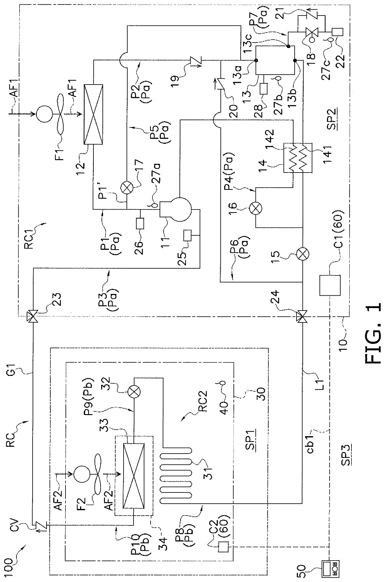
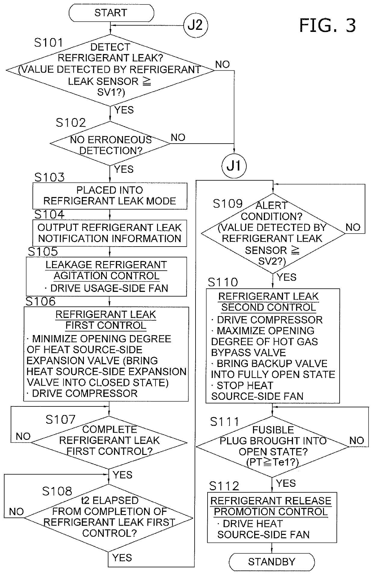
[0239]In the foregoing embodiment, the heat source-side expansion valve 15 is controlled to have the minimum opening degree, that is, brought into the closed state by the refrigerant leak first control to function as the control valve (corresponding to a first control valve in the claims) configured to prevent the flow of the refrigerant toward the usage-side refrigerant circuit RC2 upon occurrence of a refrigerant leak. Alternatively, any valve rather than the heat source-side expansion valve 15 may function as the first control valve.

[0240]For example, as in a refrigeration apparatus 100a illustrated in FIG. 5, a first electromagnetic valve 71 is disposed on a liquid-side connection pipe L1. A controller 60 performs refrigerant leak first control to bring the first electromagnetic valve 71 into a fully closed state, that is, to minimize an opening degree of the first electromagnetic valve 71. With this configuration, the first electromagnetic valve 71 may funct...

modification 2

(6-2) Modification 2

[0243]In the foregoing embodiment, the fusible plug mount pipe P7 is disposed between the receiver 13 and the fusible plug 22. In addition, the backup valve 18 and the third check valve 21 are disposed on the fusible plug mount pipe P7. In other words, the fusible plug 22 is coupled to the receiver 13 via the fusible plug mount pipe P7. However, how to mount the fusible plug 22 is not limited as long as the fusible plug 22 is capable of releasing the refrigerant to the outside of the refrigerant circuit RC from the refrigerant circuit RC, and may be appropriately changed in accordance with installation environments and design specifications.

[0244]For example, in a refrigeration apparatus 100c illustrated in FIG. 7, a fusible plug 22 may be directly connected to a receiver 13, more specifically a bypass port 13c. The refrigeration apparatus 100c does not include the fusible plug mount pipe P7, the backup valve 18, and the third check valve 21 described in the fore...

modification 3

(6-3) Modification 3

[0245]In the foregoing embodiment, the controller 60 performs the refrigerant leak second control to maximize the opening degree of the injection valve 16 and the opening degree of the hot gas bypass valve 17 and to bring the backup valve 18 into the fully open state. Moreover, the controller 60 also performs the refrigerant leak second control to drive the compressor 11 at the number of rotations for the refrigerant leak second control. With this configuration, the hot gas discharged from the compressor 11 is supplied to the receiver 13 via the hot gas pipe P5, and then is supplied from the receiver 13 to the fusible plug 22 via the fusible plug mount pipe P7. The fusible plug 22 is thus heated to the first temperature Te1. In other words, the controller 60 performs the refrigerant leak second control to cause mainly the compressor 11, the hot gas pipe P5, and the fusible plug mount pipe P7 to function as the heating unit configured to directly or indirectly app...


PUM


Abstract

Provided is a refrigeration apparatus with improved safety. A refrigeration apparatus includes: a compressor; a heat source-side expansion valve to be controlled to have a minimum opening degree and brought into a closed state in which the heat source-side expansion valve maximizes prevention of a flow of a refrigerant toward a usage-side refrigerant circuit; a fusible plug; a controller; and a refrigerant leak detector configured to detect a refrigerant leak at the usage-side refrigerant circuit. The fusible plug is disposed in a refrigerant circuit, and is brought into an open state to allow the refrigerant circuit to communicate with an external space. When the refrigerant leak detector detects a refrigerant leak at the usage-side refrigerant circuit, the controller performs refrigerant leak first control to bring the heat source-side expansion valve into the closed state, and performs refrigerant leak second control to bring the fusible plug into the open state.

Description

TECHNICAL FIELD[0001]The present disclosure relates to a refrigeration apparatus.BACKGROUND ART[0002]In a conventional refrigeration apparatus, for example, damage to or faulty installation of a component constituting a refrigerant circuit may cause a refrigerant leak from the refrigerant circuit. Such a refrigeration apparatus therefore requires measures for ensuring safety upon occurrence of a refrigerant leak.[0003]For example, Patent Literature 1 (JP H05-118720 A) discloses the following method as one of the measures against a refrigerant leak. Upon detection of a refrigerant leak, a predetermined control valve (e.g., a valve whose opening degree is controllable, such as an electromagnetic valve or an electric valve) in a refrigerant circuit is controlled to have a minimum opening degree, that is, is brought into a closed state. The control valve thus prevents a flow of the refrigerant toward a usage unit, and suppresses occurrence of an additional refrigerant leak at a usage-si...

Claims


Application Information

Patent Timeline
Patent Type & Authority Applications(United States)
IPC IPC(8): F25B1/04F25B49/02
CPCF25B1/00F25B49/02F25B43/006F24F11/36F25B2500/221F25B45/00F25B2400/19F25B41/20F25B41/24F25B1/04F25B2400/04
Inventor SAKAE, SATORUMEZAKI, TAKENORI
Owner DAIKIN IND LTD
Why Eureka
Try Eureka