
Steering wheel

Active Publication Date: 2020-01-02
TOYODA GOSEI CO LTD
View PDF0 Cites 11 Cited by
  • Summary
  • Abstract
  • Description
  • Claims
  • Application Information

AI Technical Summary

Benefits of technology

The present invention provides a steering wheel that improves touch feeling and appearance by reducing friction between the gripping portion and the palm, and reducing external light reflection on the cover. This is achieved by forming a covering portion around the light guide body, with a hole for reducing external light reflection. Additionally, the covering portion covers the cover, reducing the amount of external light reflected by the cover. The improved appearance and touch feeling make the steering wheel more comfortable and user-friendly.

Problems solved by technology

Further, when the ring portion is irradiated with external light, the portion where the cover is exposed in the ring portion appears brighter than the portion where the cover is not exposed, which would deteriorate an appearance of the ring portion.
These problems may occur in a steering wheel of a conveyance other than a vehicle or a steering wheel that presents information at a portion other than the ring portion, as long as the steering wheel presents information by light at a portion (gripping portion) gripped by a driver during steering of a conveyance.
Incidentally, the hole is formed in the covering portion, so that a member of the gripping portion on the inner side of the covering portion can be seen through the hole from the outside of the gripping portion, which might deteriorate appearance quality of the gripping portion.
Therefore, as compared with a case where the surface of the cover on the driver side is formed to be smooth and slippery, or a case where the light diffusion sheet is not disposed between the surface of the cover on the driver side and the covering portion, the members of the gripping portion inside the covering portion are more difficult to be seen from the outside of the gripping portion through the hole.

Method used


Image

  • Steering wheel
  • Steering wheel
  • Steering wheel

Examples


first embodiment

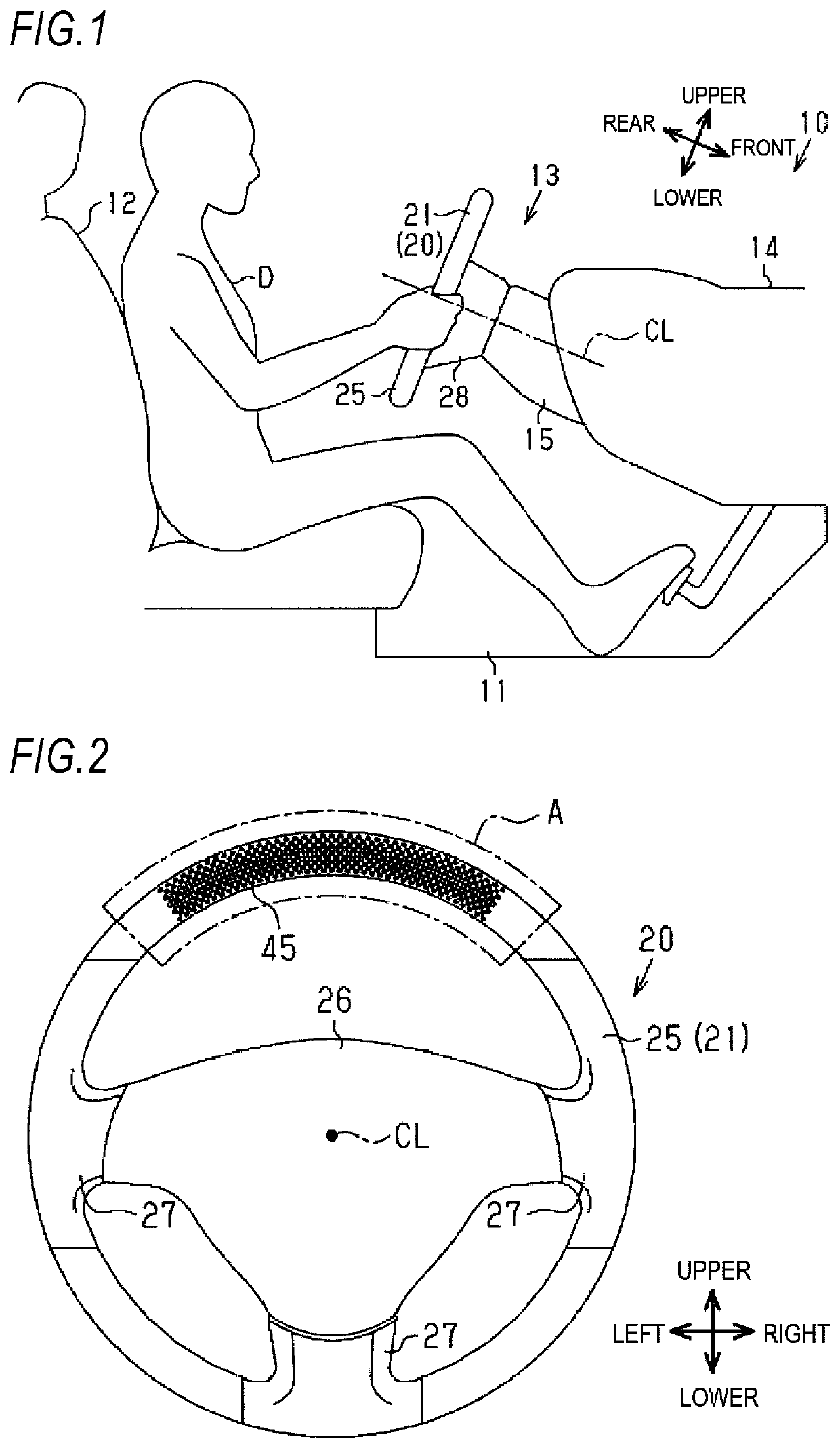
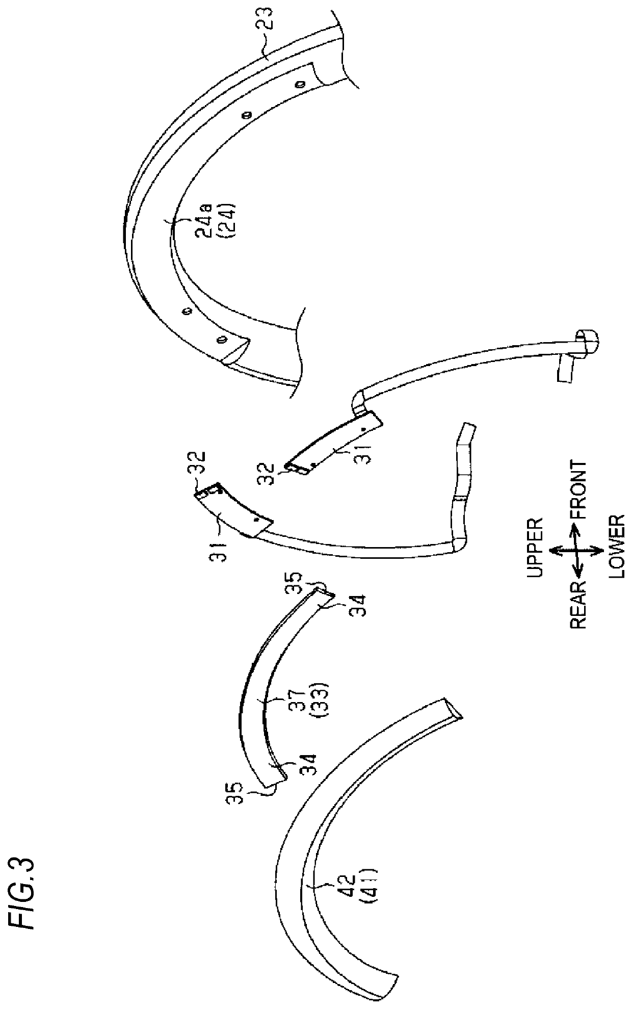
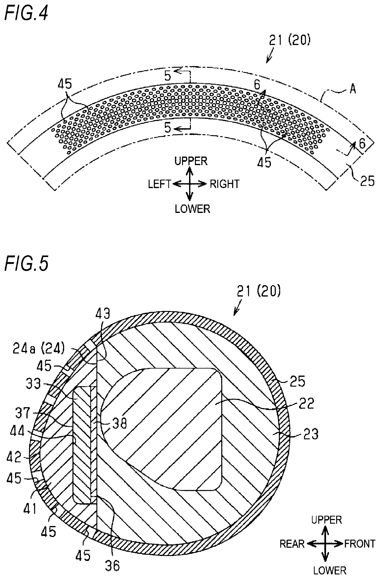
[0027]Hereinafter, a steering wheel for a vehicle according to a first embodiment is described with reference to FIGS. 1 to 7B.

[0028]As illustrated in FIG. 1, in front of a driver seat 12 in a vehicle interior 11, a steering device 13 operated by a driver D is provided so as to change a traveling direction of a vehicle 10 which is an example of a conveyance. The steering device 13 includes a steering column 15 attached to a vehicle body 14 and a steering wheel 20 rotatably disposed on a rear side of the steering column 15. A steering shaft (not illustrated) that is configured to transmit rotation of the steering wheel 20 to a steering gear box (not illustrated) is disposed in the steering column 15. The steering shaft is disposed in a state of being inclined so as to be higher toward the rear side and rotates about a central axis line CL.

[0029]In the present specification, when each part of the steering wheel 20 is described, the central axis line CL is used as a reference. A direct...

second embodiment

[0066]Next, a steering wheel for a vehicle according to a second embodiment is described with reference to FIG. 8.

[0067]In the second embodiment, in addition to configurations of the first embodiment, a light diffusion sheet 51 is disposed between the rear surface 42 of the cover 41 and the surface layer 25. The light diffusion sheet 51 has transparency to light that passes through the cover 41. At least a rear surface, which is a surface of the light diffusion sheet 51 on the driver D side, is formed to be rougher than the rear surface 42 of the cover 41. The configurations other than the above are the same as those of the first embodiment. Therefore, the same elements as those described in the first embodiment are denoted by the same reference numerals, and repetitive descriptions thereof are omitted.

[0068]According to the second embodiment, in addition to the same operational effects as those in the first embodiment, the following operational effects can be obtained.

[0069]Light e...

third embodiment

[0071]Next, a steering wheel for a vehicle according to a third embodiment is described.

[0072]Although not illustrated, in the third embodiment, instead of the light diffusion sheet 51 in the second embodiment, the rear surface 42 of the cover 41 is formed as rough as the rear surface of the light diffusion sheet 51. In other words, the rear surface 42 of the cover 41 is formed rougher than a surface other than the rear surface 42 of the cover 41. In the third embodiment, the rough surface is formed by performing blast treatment on the rear surface 42 of the cover 41 as a target surface. The blast treatment is a method in which a solid metal, a mineral abrasive material or a vegetable abrasive material is sprayed onto the target surface at a high speed to roughen the target surface. The configurations other than the above are the same as those of the second embodiment.

[0073]According to the third embodiment, the same operational effects as those in the second embodiment can be obtai...


PUM


Abstract

A steering wheel includes a gripping portion that is gripped by a driver when a conveyance is steered, a light source that is disposed inside the gripping portion and is configured to emit light, a light guide body that is disposed inside the gripping portion such that an end portion of the light guide body faces the light source, the light guide body including an emission surface that is configured to emit light from the light source and incident on the end portion and that is formed on a surface on a driver side, and a covering portion that surrounds the light guide body and forms an outer layer portion of at least a part of the gripping portion around the light guide body. The covering portion is formed with a hole, through which light emitted from the emission surface passes.

Description

CROSS-REFERENCE TO RELATED APPLICATION[0001]This application claims priority from Japanese Patent Application No. 2018-122361, filed on Jun. 27, 2018, the entire subject matter of which is incorporated herein by reference.TECHNICAL FIELD[0002]The present invention relates to a steering wheel that is operated when steering a conveyance which is a vehicle or the like, and more particularly, to a steering wheel having a function of presenting information by light.BACKGROUND ART[0003]JP-A-2017-109521 describes a steering wheel of a conveyance which is a vehicle or the like and having a function of presenting information by light. In the steering wheel, a light source is disposed in a ring portion that is gripped and operated when the vehicle is steered. Further, in the ring portion, a light guide body is disposed such that an end portion of the light guide body faces the light source. An emission surface, which emits light from the light source and incident on the end portion, is formed...

Claims


Application Information

Patent Timeline
IPC IPC(8): B60Q3/283B60Q3/64F21V8/00B62D1/06
CPCG02B6/0043B60Q3/283B60Q3/64G02B6/0051B62D1/06B62D1/046B60K35/00B60Q9/00B60Q3/62G02B6/001B60K35/10B60K2360/332B60K2360/336B60K35/60B60K2360/782
Inventor KAMEI, SHUNSUKEMIZUNO, YOSHIOABO, HAYATO
Owner TOYODA GOSEI CO LTD
Learn More