Scale configuration for inductive position encoder

a technology of inductive position and encoder, which is applied in the direction of electrical/magnetically converting sensor output, measuring devices, instruments, etc., can solve the problems that systems may be limited in their ability to provide certain combinations of features, and achieve better signal-to-noise ratio, reduce error components, and improve detector signal characteristics

Pending Publication Date: 2020-01-02
MITUTOYO CORP
View PDF4 Cites 13 Cited by
  • Summary
  • Abstract
  • Description
  • Claims
  • Application Information

AI Technical Summary

Benefits of technology

[0006]The scale extends along the measuring axis direction and includes a periodic scale pattern comprising at least a first type of signal modulating elements. The periodic scale pattern has a spatial wavelength W1. The signal modulating elements of the first type comprise similar conductive plates or similar conductive loops that are located along the measuring axis direction corresponding to the spatial wavelength W1. The detector portion is configured to be mounted proximate to the periodic scale pattern and to move along the measuring axis direction relative to the periodic scale pattern. In various implementations, the detector portion includes a field generating coil and a set of sensing elements. The field generating coil is fixed on a substrate and surrounds an interior area that is aligned with the periodic scale pattern of signal modulating elements during operation. As used herein, the term “surrounds” may mean completely surrounds, or partially surrounds, in various implementations. The only constraint is that the field generating coil is configured to generate a changing magnetic flux in the interior area in response to a coil drive signal, in a manner that supports operation according to the principles disclosed and claimed herein. The set of sensing elements is arranged along the measuring axis direction and fixed on the substrate. The members of the set of sensing elements comprise conductive loops or conductive loop portions having a nominal sensing element width dimension DSEN along the measuring axis direction, at least for that portion of the sensing element that is aligned with or overlaps the interior area surrounded by the fil...

Problems solved by technology

However, such systems may be limited in their ability to provide certain combinations of features desired by ...

Method used


Image

  • Scale configuration for inductive position encoder
  • Scale configuration for inductive position encoder
  • Scale configuration for inductive position encoder

Examples


Embodiment Construction

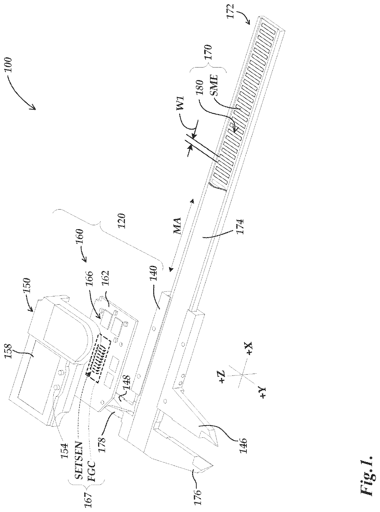
[0018]FIG. 1 is an exploded isometric view diagram of a hand tool type caliper 100 including a scale member 172 and slider assembly 120. The scale member 172 may comprise a spar of roughly rectangular cross-section including a scale 170 positioned in a groove therein. The slider assembly 120 may include a base 140, an electronic assembly 160, and a cover 150, described in greater detail below. The electronic assembly 160 may include a detector portion 167 and a signal processing configuration 166 arranged on a substrate 162. A resilient seal (not shown) may be compressed between the cover 150 and the substrate 162 to exclude contamination from the circuitry and connections. The scale 170, the detector portion 167 and the signal processing configuration 166 work cooperatively to provide an inductive electronic position encoder that is usable to measure a relative position between two elements (e.g., between the scale member 172 and slider assembly 120) along a measuring axis directio...


PUM


Abstract

An inductive type position encoder includes a scale, a detector portion and a signal processor. The scale includes a periodic pattern of signal modulating elements (SME) arranged along a measuring axis, with a spatial wavelength W1. One type of SME in the pattern comprises similar conductive plates or loops. The detector portion comprises sensing elements and a field generating coil that generates a changing magnetic flux. The sensing elements may comprise conductive loop portions arranged along the measuring axis and configured to provide detector signals which respond to a local effect on the changing magnetic flux provided by adjacent SME's. In various implementations, the first type of SMEs have an average dimension DSME along the measuring axis direction that is greater than DSEN and at least .55*W1 and at most 0.8*W1, which provides advantageous detector signal characteristics.

Description

BACKGROUNDTechnical Field[0001]This disclosure relates to measurement instruments and, more particularly, to inductive position encoders that may be utilized in precision measurement instruments.Description of the Related Art[0002]Various encoder configurations may include various types of optical, capacitive, magnetic, inductive, movement and / or position transducers. These transducers use various geometric configurations of a transmitter and a receiver in a read head to measure movement between the read head and a scale.[0003]U.S. Pat. No. 6,011,389 (the '389 patent) describes an induced current position transducer usable in high accuracy applications; U.S. Pat. Nos. 5,973,494 (the '494 patent) and U.S. Pat. No. 6,002,250 (the '250 patent) describe incremental position inductive calipers and linear scales, including signal generating and processing circuits; and U.S. Pat. Nos. 5,886,519 (the '519 patent), U.S. Pat. No. 5,841,274 (the '274 patent), and U.S. Pat. No. 5,894,678 (the '...

Claims


Application Information

Patent Timeline
IPC IPC(8): G01D5/20
CPCG01D5/202G01B3/205G01D5/14G01D5/2053
Inventor COOK, TED STATONHITCHMAN, JAMES ALLENKATO, YOSHIAKI
Owner MITUTOYO CORP
Why Eureka
Try Eureka