Supercharge Your Innovation With Domain-Expert AI Agents!

Imaging ellipsometer system utilizing a tunable acoustic gradient lens

a gradient lens and ellipsometer technology, applied in the field of precision metrology, can solve the problems of affecting repeatability and/or accuracy, affecting the repeatability and/or accuracy of motorized focusing mechanism scanning techniques, and certain optical components, such as analyzers, may include unique defects

Active Publication Date: 2020-01-02
MITUTOYO CORP
View PDF0 Cites 2 Cited by
  • Summary
  • Abstract
  • Description
  • Claims
  • Application Information

AI Technical Summary

Benefits of technology

The patent describes an imaging ellipsometer system that uses a special lens to measure the refractive index and thickness of layers on a workpiece. The system includes a light source, polarizer, compensator, analyzer, and camera. The lens has a special property that allows it to focus light at a specific position, which is controlled by a piezoelectric actuator. The system measures the phase and magnitude of light reflected from the workpiece, and can determine the refractive index and thickness of layers on the workpiece based on these measurements. The technical effect of this system is to provide a non-destructive and accurate method for measuring the properties of optical films and coatings on workpieces.

Problems solved by technology

As described in the Accurion Publication, one general issue with imaging ellipsometry is related to the inclined observation angle (i.e., the surface of the workpiece that is being inspected is at an angle relative to the CCD camera, for which different portions of the surface are at different focus distances relative to the camera).
While imaging ellipsometer systems such as those described above are able to provide a digitized image that is in focus, the motorized focusing mechanism scanning techniques typically require a certain amount of time to be performed.
In addition, in certain instances the mechanical translation and altering of the relative positions of the components of the system (e.g., utilizing the motorized focusing mechanism) may have detrimental effects on repeatability and / or accuracy when used for acquiring inspection images (e.g., fixed focus inspection images) which are used for precision measurements (e.g., for accuracies on the order of a few micrometers) and the like.
In addition, as described in the '296 patent, certain optical components, such as analyzers, may include unique defects which may only be determined by complex calibration procedures.
Since the intensities of the phase shifted beams must add vectorially on a common pixel for accurate readings, beam walking may present a deficiency in the precision of ellipsometric systems.

Method used


Image

  • Imaging ellipsometer system utilizing a tunable acoustic gradient lens
  • Imaging ellipsometer system utilizing a tunable acoustic gradient lens
  • Imaging ellipsometer system utilizing a tunable acoustic gradient lens

Examples


Embodiment Construction

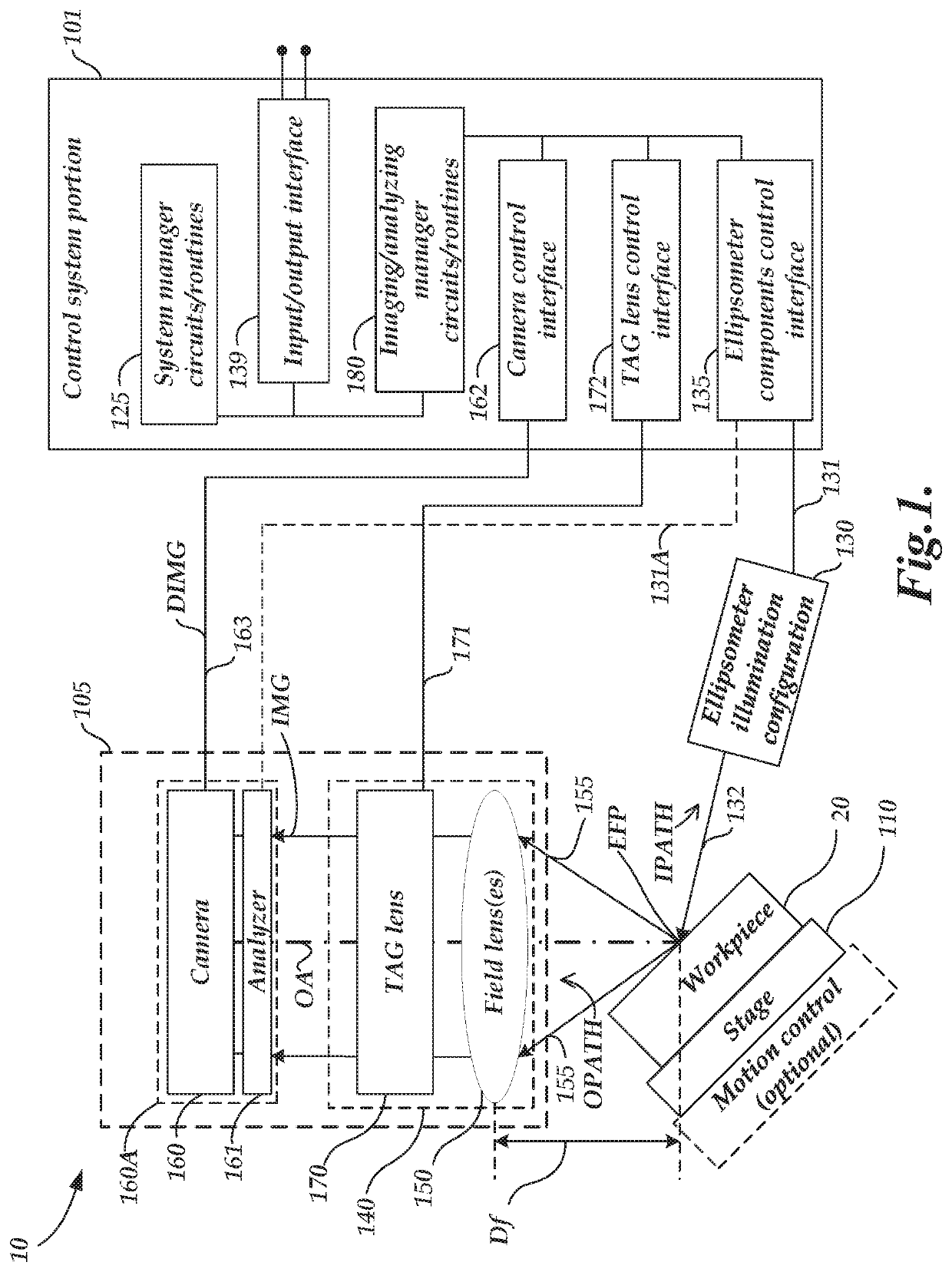
[0014]FIG. 1 is a block diagram of an imaging ellipsometer system 10 including an optical imaging system 105, an ellipsometer illumination configuration 130, a workpiece stage 110 and a control system portion 101. In various implementations, the imaging ellipsometer system 10 may be adapted to a host system (e.g., machine vision), or used as a standalone system, and may be operated according to principles disclosed herein and in the incorporated references. The imaging ellipsometer system 10, including the optical imaging system 105, the ellipsometer illumination configuration 130, and the workpiece stage 110, may generally be controlled by the control system portion 101 to inspect and / or image a workpiece 20.

[0015]The optical imaging system 105 includes a camera 160, an analyzer 161 (e.g., comprising a polarizer), one or more field lenses 150 (e.g., including an interchangeable objective lens), and a tunable acoustic gradient (“TAG”) lens 170. A brief background is described below ...


PUM

PropertyMeasurementUnit
anglesaaaaaaaaaa
anglesaaaaaaaaaa
anglesaaaaaaaaaa

Abstract

A imaging ellipsometer system is provided including a lens configuration with tunable acoustic gradient index of refraction (“TAG”) lens. The imaging ellipsometer system further includes a light source, a polarizer, a compensator, an analyzer and a camera. Light from the light source passes through the polarizer and is directed toward a workpiece. In various implementations, the compensator is located and configured to elliptically polarize the light either before or after the light is reflected from the workpiece. The lens configuration receives the reflected workpiece light and the TAG lens is controlled to provide a modulation of a focus position. The camera receives workpiece light that passes through the TAG lens and the analyzer during an image exposure and provides a corresponding camera image. An ellipsometry analysis is performed (e.g., to determine at least one of a refraction index, or a thickness of one or more layers of the workpiece, etc.)

Description

BACKGROUNDTechnical Field[0001]This disclosure relates to precision metrology and, more particularly, to the use of imaging ellipsometer systems for inspection and dimensional metrology.Description of the Related Art[0002]In ellipsometry, polarized light is shined at an angled surface, and the reflected light is analyzed to determine the magnitude and phase of light reflected by the two constituent, orthogonal polarizations (s- and p-). Since the surface reflectivity depends on polarization and angle (e.g., as indicated by Fresnel equations), the analyzed light can be used to determine the refractive index of the surface. In various implementations, by varying the light source wavelength, material dispersion can be derived. Or, if the surface is made up of a thin optical film, or a stack of films, a model can be used to determine the refractive indices and thicknesses of those layers. U.S. Pat. No. 5,754,296, which is hereby incorporated herein by reference in its entirety, disclose...

Claims


Application Information

Patent Timeline
Patent Type & Authority Applications(United States)
IPC IPC(8): G02F1/29H04N5/238G01N21/21H04N23/75
CPCG01N21/211H04N5/238G02F1/29H04N23/56H04N23/673H04N23/73H04N23/74G02F1/33
Inventor SUMMERS, JOSEPH ANDREW
Owner MITUTOYO CORP
Features
  • R&D
  • Intellectual Property
  • Life Sciences
  • Materials
  • Tech Scout
  • Unparalleled Data Quality
  • Higher Quality Content
  • 60% Fewer Hallucinations
Learn More