Normalized metadata generation device, object occlusion detection device and method

Active Publication Date: 2020-01-02
CHUNG ANG UNIV IND ACADEMIC COOP FOUND
View PDF5 Cites 11 Cited by
  • Summary
  • Abstract
  • Description
  • Claims
  • Application Information

AI Technical Summary

Benefits of technology

[0053]According to the embodiments of the present invention, the normalized metadata generation device and method accurately detects an object of interest from various images obtained by various kinds of cameras of a multi camera based video surveillance system for searching an object of interest in a wide range The extracted normalized metadata of the object of interest can be extracted, and no special pattern or depth measurement is required for camera calibration.
[0054]Also, by providing the o

Problems solved by technology

A common challenge with such conventional video indexing and retrieval methods is to summarize rare events from many data sets generated using multiple cameras including various types of cameras.
However, the lack of normalized object information during retrieval has a problem of preventing accurate recognition of the same object

Method used


Image

  • Normalized metadata generation device, object occlusion detection device and method
  • Normalized metadata generation device, object occlusion detection device and method
  • Normalized metadata generation device, object occlusion detection device and method

Examples


Example

First Embodiment

[0174]When the number of sets of foot and head detected is smaller than N, the vanishing point and the vanishing line may be predicted using the background line information.

[0175]For example, three vanishing points may be selected from intersections that intersect background line information using the RANSAC algorithm. At least one of the three selected vanishing points is determined as a vertical vanishing point. Then, a line connecting the remaining two vanishing points of the three vanishing points may be determined as a horizontal vanishing line.

Example

Second Embodiment

[0176]When the number of sets of foot and head detected is greater than N and object movement is linear, the object occlusion detection device 100 can predict the vertical vanishing point using the foot and head positions of the object.

[0177]The vertical vanishing point may be determined at the intersection of the line connecting the foot and the head position, as shown in FIG. 34. However, since one horizontal vanishing point is predicted when the object moves linearly, it is impossible to predict the horizontal vanishing line. Therefore, the object occlusion detection device 100 may predict the vanishing line using the background line information.

Example

Third Embodiment

[0178]When the number of sets of foot and head detected is greater than N and object movement is not linear, the object occlusion detection device 100 may predict the vanishing point and the vanishing line using the foot and head positions. A line connecting the positions of two feet of the detected foot positions (referred to as a foot line) and a line connecting the positions of two heads (referred to as a head line) are used to predict the horizontal vanishing point.

[0179]As a result, the horizontal vanishing line may be predicted using two horizontal vanishing points, as shown in FIG. 34.

[0180]In step 125, the object occlusion detection device 100 calibrates the camera parameters using the predicted vanishing point and the vanishing line.

[0181]For example, the object occlusion detection device 100 may calibrate camera parameters using two predicted vertical vanishing points and the horizontal vanishing line. This can be expressed by Equation 38.

f=(a3 / a2-py)(vy-py...


PUM


Abstract

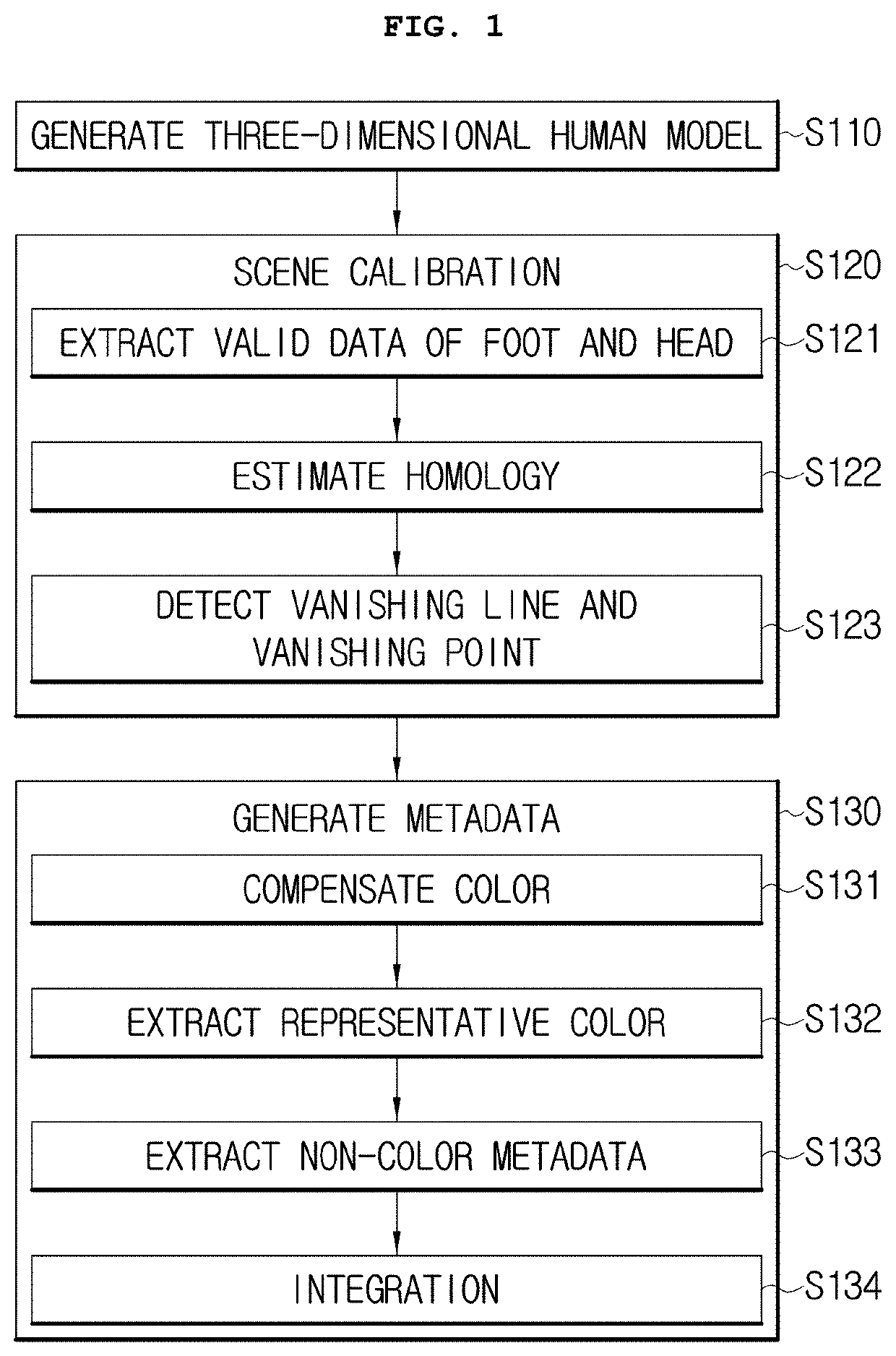
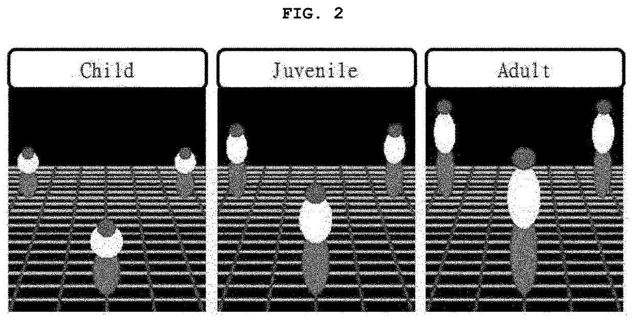
Disclosed a normalized metadata generation device, and object occlusion detection device and method. A normalized metadata generation method includes generating a multi-ellipsoid based three-dimensional human model using perspective features of a plurality of two-dimensional images obtained by the multiple cameras, performing scene calibration based on the three-dimensional human model to normalize object information of the object included in the two-dimensional images, and generating normalized metadata of the object from the two-dimensional images on which the scene calibration is performed.

Description

CROSS REFERENCE TO RELATED APPLICATIONS[0001]This present application is a national stage filing under 35 U.S.C § 371 of PCT application number PCT / KR2017 / 002459 filed on Mar. 7, 2017 which is based upon and claims the benefit of priority to Korean Patent Application Nos. 10-2016-0124768 and 10-2016-0133474 filed on Sep. 28, 2016 and Oct. 14, 2016, respectively, in the Korean Intellectual Property Office. The disclosures of the above-listed applications are hereby incorporated by reference herein in their entirety.TECHNICAL FIELD[0002]The present invention relates to a normalized metadata generation device and method, and an object occlusion detection device and method capable of detecting an occluded state of an object through image analysis.BACKGROUND ART[0003]A multi-camera based video surveillance system produces huge amounts of data every day. In order to detect meaningful information from the huge amounts of data, the normalized metadata should be extracted to recognize and tr...

Claims


Application Information

Patent Timeline
IPC IPC(8): G06T7/80G06F16/583G06K9/46G06K9/62G06T7/536G06T7/60G06K9/00G06T17/00G06V10/56
CPCG06T7/536G06T2207/10016G06T17/00G06K9/00369G06K9/4652G06K9/00771G06F16/5854G06T7/80G06K9/6223G06T7/60G06T2207/30232G06T2207/30196G06T2207/10024G06V40/103G06V20/52G06V10/56G06V10/763G06F18/23213
Inventor PAIK, JOON KIJUNG, JAE HOONYOON, IN HYELEE, SEUNG WON
Owner CHUNG ANG UNIV IND ACADEMIC COOP FOUND
Why Eureka
Try Eureka