Device, method and system for on-chip generation of a reference clock signal

a reference clock and clock signal technology, applied in the direction of generating/distributing signals, pulse automatic control, instruments, etc., can solve the problems of limited maximum frequency of base clock signals, external clock control logic, and often constrained cpu dies

Active Publication Date: 2020-01-02
INTEL CORP
View PDF6 Cites 10 Cited by
  • Summary
  • Abstract
  • Description
  • Claims
  • Application Information

AI Technical Summary

Problems solved by technology

However, CPU dies in existing computer architectures are dependent on external clock control logic to implement this type of overclocking or underclocking.
Furthermore, CPU dies are often constrained by external clock control logic which is not designed for a sufficiently wide range of possible frequencies for the base clock.
Further still, the maximum allowable frequency of a base clock signal is often limited by the type of interconnect which is used to communicate the base clock signal to a CPU die.

Method used


Image

  • Device, method and system for on-chip generation of a reference clock signal
  • Device, method and system for on-chip generation of a reference clock signal
  • Device, method and system for on-chip generation of a reference clock signal

Examples


Embodiment Construction

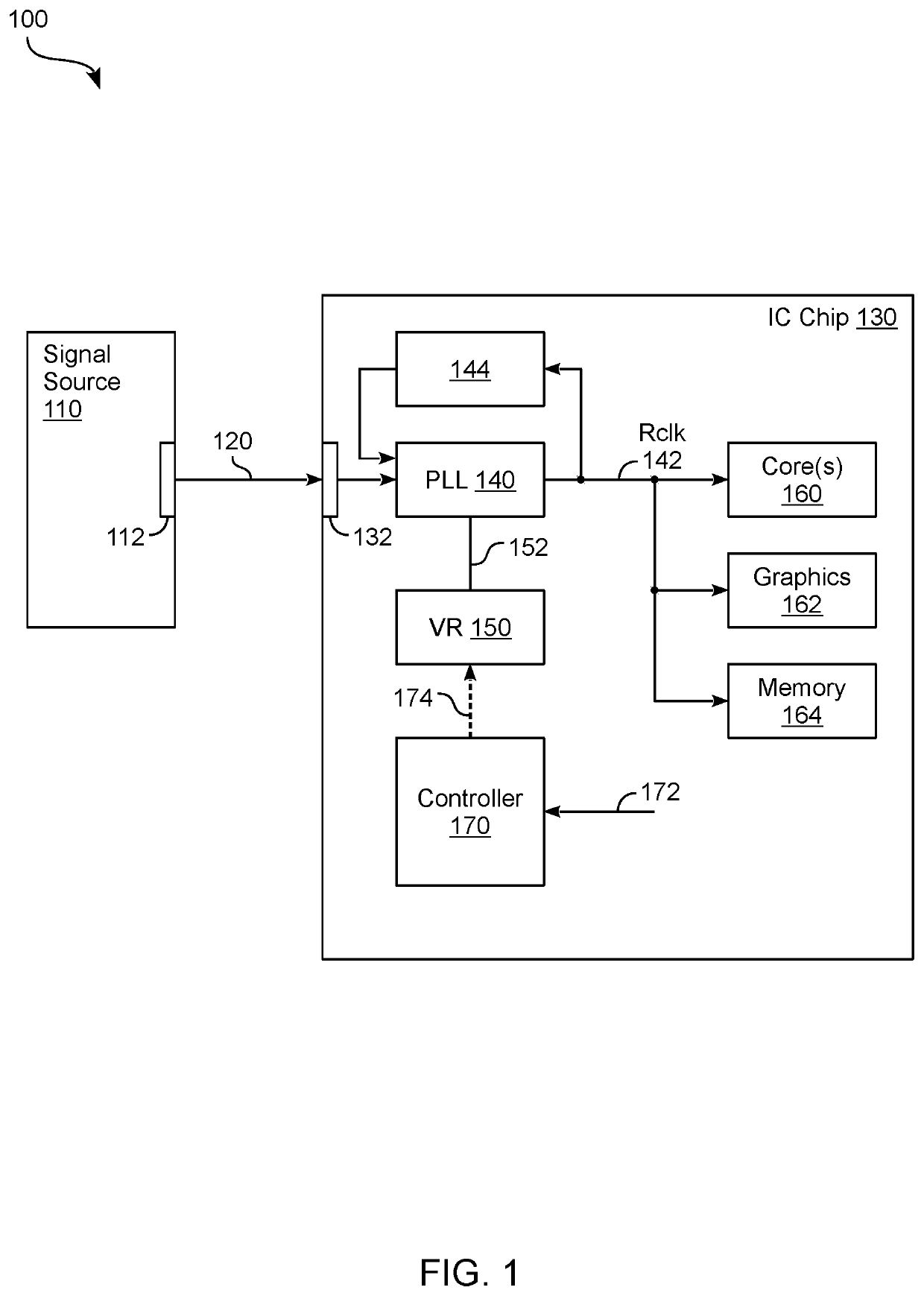
[0012]Embodiments discussed herein variously provide techniques and mechanisms for an integrated circuit (IC) chip to control local generation of a clock signal which is used by a processor and / or other resources of the IC chip. Such local generation of a clock signal by an IC chip may be based on a cyclical signal which is provided to the IC chip by an external source. In some embodiments, the cyclical signal received by the IC chip is an analog signal generated (for example) by a crystal oscillator.

[0013]Such a clock signal may provide “reference clock” functionally similar to that of a type of digital clock signal (often referred to as a “base clock signal”) which, in conventional clocking architectures, is provided from off-chip to an IC chip. As compared to these conventional clocking architectures, on-chip generation of a reference clock signal enables a significantly wider range of available clock frequencies. To accommodate such a wider range, some embodiments variously enab...


PUM


Abstract

Techniques and mechanisms for an integrated circuit (IC) chip to generate a clock signal for use by one or more resources of the IC chip. In an embodiment, a clock signal is generated with phase-locked loop (PLL) circuitry of an IC chip based on a cyclical signal which is provided to the IC chip by an external source. A supply voltage provided to the PLL circuitry is automatically updated based on one of a requested frequency for the clock signal, a frequency of the received cyclical signal, or a voltage of a control signal used by a voltage controlled oscillator of the PLL circuitry. In another embodiment, a series of incremental changes to a frequency of the clock signal is automatically performed according to a predefined overclocking scheme or underclocking scheme.

Description

BACKGROUND1. Technical Field[0001]The present invention relates generally to the clocking of integrated circuitry and more specifically, but not exclusively, to an automatic configuration of circuitry for generating a reference clock signal.2. Background Art[0002]Conventional computer architectures variously provide a central processing unit (CPU) die and some external source which is coupled to send to the CPU die a digital clock signal—often referred to as a “base clock”—for use in generating one or more local clock signals. One or more synchronous domains of such a CPU die variously operate each based on a respective local clock signal which, in turn, is based on the received base clock signal.[0003]Overclocking or underclocking of many synchronous domains of a CPU die can be efficiently achieved by changing a frequency of the base clock signal. However, CPU dies in existing computer architectures are dependent on external clock control logic to implement this type of overclockin...

Claims


Application Information

Patent Timeline
Patent Type & Authority Applications(United States)
IPC IPC(8): G09G5/00H03L7/08G06F1/04G06F1/26
CPCG09G5/008G06F1/04G06F1/26H03L7/08G09G5/18H03L7/183H03L7/23
Inventor KURD, NASSERRAGLAND, DANIELAMBARDEKAR, AMEYAFALLIN, JOHNMOSALIKANTI, PRAVEENGROSSNICKLE, VAUGHN J.
Owner INTEL CORP
Why Eureka
Try Eureka