
Monitoring cardiac blood flow balance relationship between the right and left heart chambers and cardiac regulation

Inactive Publication Date: 2020-01-09
KHAIR MOHAMMAD MOHAMMAD
View PDF0 Cites 4 Cited by
  • Summary
  • Abstract
  • Description
  • Claims
  • Application Information

AI Technical Summary

Benefits of technology

The present invention provides a system and method for measuring the balance between the left and right chambers of the heart using arterial pulse signals. This balance parameter is used to assess a patient's health condition and can also be used to generate a full arterial pulse signal, which is useful in analyzing the ventricular supply factor without atrial interaction effects. The system identification techniques are used to model the transfer function relationship between the peripheral artery and aortic or pulmonary artery signals. Overall, the invention improves the accuracy and performance of measuring cardiac blood flow balance parameters and provides a more reliable tool for assessing patient health.

Problems solved by technology

Often the performance of the left side of the vascular system is analyzed separately from the right side, which yields weak conclusions that cannot be generalized.
Traditional models that failed to take into account the simultaneous effects of the left and right heart cycles tend to bias the attribution of the dynamics it models to one side over the other, and therefore fail to represent the true dynamics fully.

Method used


Image

  • Monitoring cardiac blood flow balance relationship between the right and left heart chambers and cardiac regulation
  • Monitoring cardiac blood flow balance relationship between the right and left heart chambers and cardiac regulation
  • Monitoring cardiac blood flow balance relationship between the right and left heart chambers and cardiac regulation

Examples


Embodiment Construction

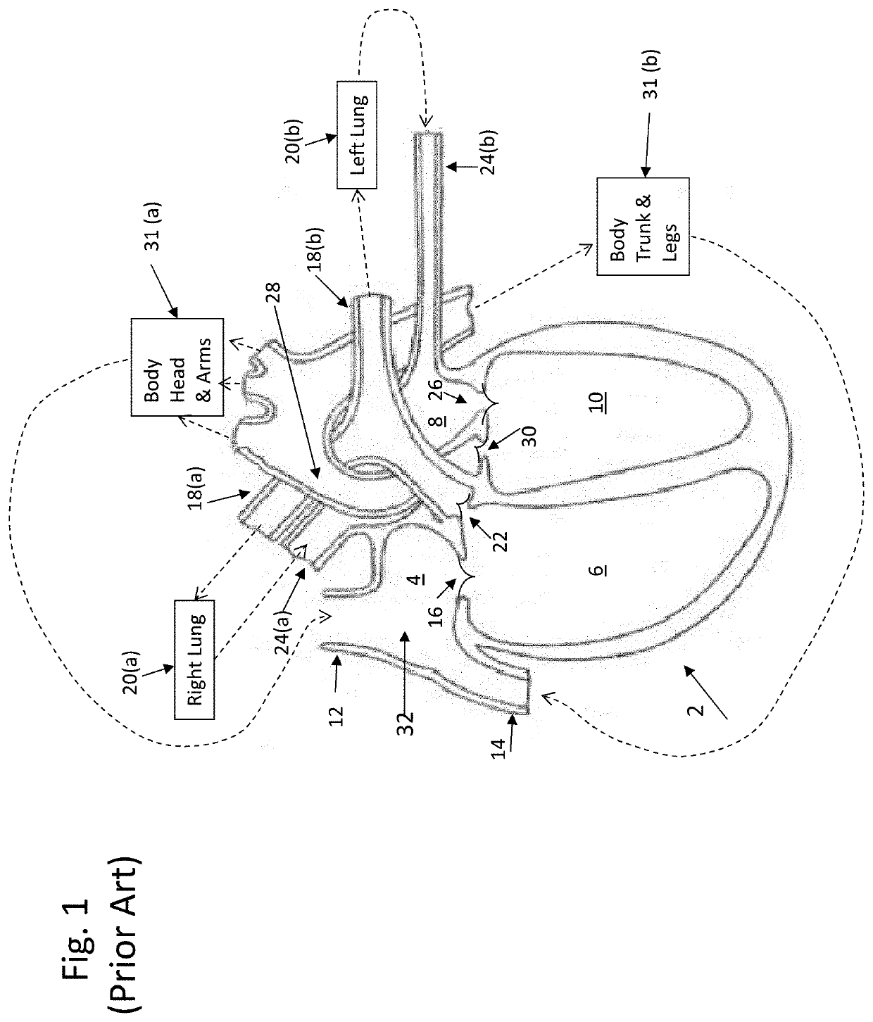
[0053]Before explaining the disclosed embodiments in detail, it is to be distinctly understood at the outset that the present invention shown in the drawings and predominantly described in detail in association with a system for measuring of cardiac blood flow balance parameter is not intended to serve as a limitation upon the scope or teachings thereof, but is to be considered merely for the purpose of convenience of illustration of one example of its application. In particular, the present invention may be applied to any other suitable physiological monitoring systems, such as oximetry systems, ECG systems, and any other suitable for monitoring of a patient's liver, heart, lungs, brain, kidneys and other organs of the body.

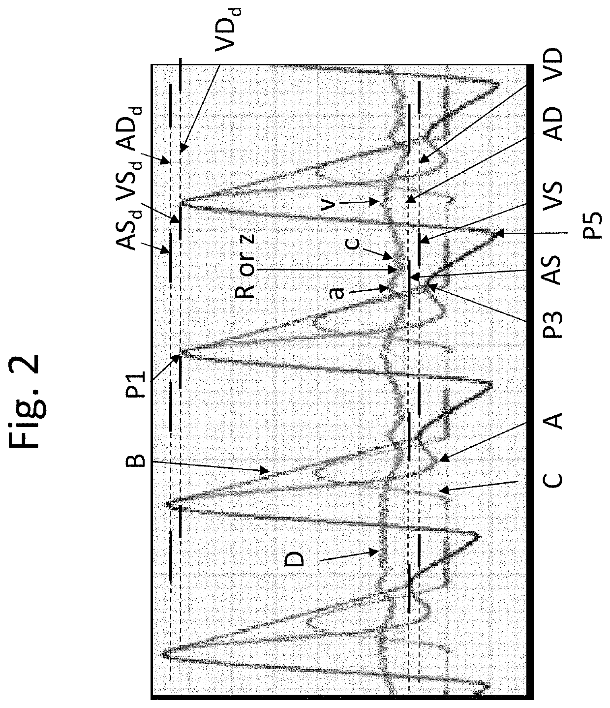
[0054]Historically, the dicrotic notch was thought to represent a reflection of a fast pressure pulse that is generated when the aortic valve opens above its cracking pressure, and blood pressure reflecting backward from the arterial side back toward the aorta. ...


PUM


Abstract

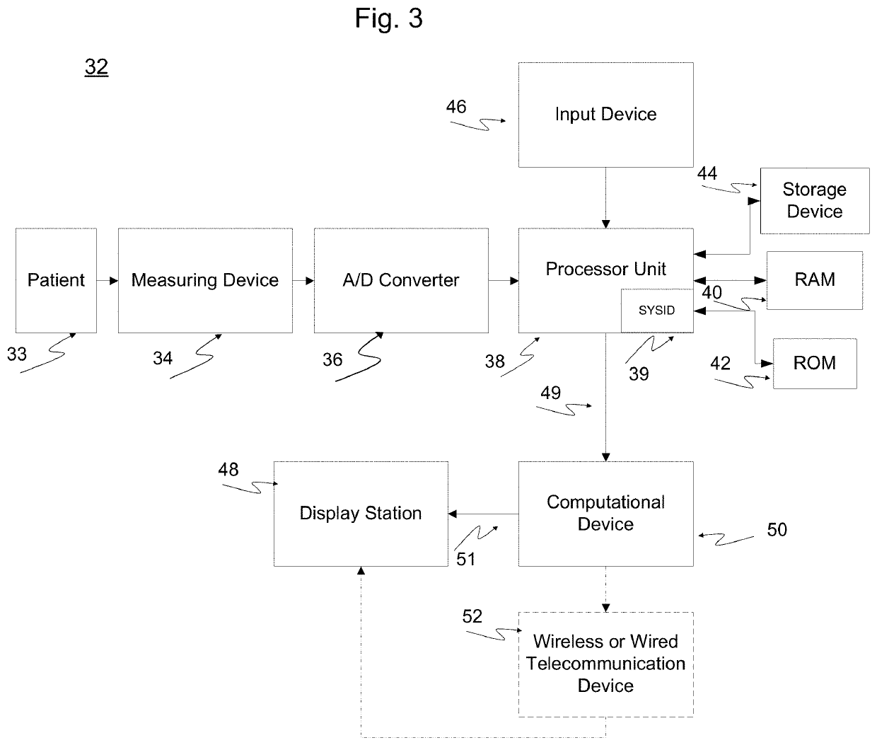
A system for measuring of cardiac blood flow balance parameter between the right chamber of the heart and the left chamber of the heart includes a sensor device for measuring one of blood pressure and blood flow rate and blood constituent concentration of a patient so as to generate an arterial pulse signal. A processing unit is responsive to the arterial pulse signal for generating a full arterial pulse signal, an arterio-venous pulse signal, and a balance parameter, including a balance ratio and a balance trend, and a pulse variability parameter. A computational device is responsive to the balance parameter for further generating a set of physiological parameters. A display station device is responsive to the set of physiological parameters from the computational device for displaying meaningful information.

Description

CROSS-REFERENCE TO RELATED APPLICATIONS[0001]This application is a non-provisional patent application which herein includes by reference and claims the benefits of provisional application 62 / 529,091 filed on Jul. 6, 2017, and provisional application Ser. No. 61 / 700,892 filed on Sep. 14, 2012, and non-provisional application US 2015 / 0018632 filed on Jul. 15, 2013, and non-provisional application US 2015 / 0025328 filed Jul. 19, 2013, and non-provisional application US 2015 / 0031969 filed Jul. 24, 2013.BACKGROUND OF THE INVENTION1. Technical Field[0002]This invention relates generally to methods, devices, and systems used in the field of cardiovascular medicine for clinically assessing of a patient's health condition. More particularly, it relates to a new and improved system and method for monitoring cardiac blood flow balance between the right and left heart chambers based on arterial pulse waveforms representing blood pressure or flow or constituent concentration per cardiac cycle.[00...

Claims


Application Information

Patent Timeline
IPC IPC(8): A61B5/02A61B5/026A61B5/028A61B8/06A61B5/0275A61B5/0215A61B5/022A61B5/00A61B5/08A61B5/20
CPCA61B5/02241A61B5/201A61B5/0261A61B5/7278A61B5/028A61B8/06A61B5/02755A61B5/6876A61B5/0215A61B2560/0475A61B5/0002A61B5/742A61B5/746A61B5/7264A61B5/4839A61B5/08A61N1/36571A61B5/4866A61B5/02028A61B5/4064A61B5/7203A61N1/36564A61N1/36585A61B5/029A61B5/7242
Inventor KHAIR, MOHAMMAD MOHAMMAD
Owner KHAIR MOHAMMAD MOHAMMAD
Learn More