Vehicle control apparatus

a technology of vehicle control and actuator, which is applied in the direction of braking systems, using reradiation, instruments, etc., can solve the problems of insufficient consideration (examination) and concern, and the driver's discomfort, so as to reduce the burden on the actuator, reduce the magnitude, and reduce the magnitude

Active Publication Date: 2020-01-09
TOYOTA JIDOSHA KK
View PDF0 Cites 1 Cited by
  • Summary
  • Abstract
  • Description
  • Claims
  • Application Information

AI Technical Summary

Benefits of technology

[0057]In contrast, in the second invention apparatus, regarding the first control, although the vehicle control means decreases a differential value of the controlled braking force during the third period, the vehicle control means decreases a differential value of the controlled driving force as well. Therefore, compared to the first configuration, it becomes possible to reduce magnitudes of both of the controlled driving force and the controlled braking force applied on the vehicle during the third period. On the other hand, regarding the second control, the vehicle control means decreases a “differential value of the controlled driving force” not a “differential value of the controlled braking force”. Therefore, compared to the first configuration, it becomes possible to reduce magnitudes of both of the controlled driving force and the controlled braking force applied on the vehicle during the third period. Hence, according to the second invention apparatus, a burden on the actuators can be reduced compared to the first configuration.
[0058]As stated above, according to the second invention apparatus, a possibility of placing a burden on the actuators can be reduced as well as a possibility that the behavior of the second longitudinal force contradicts with the brake pedal operation can be reduced.

Problems solved by technology

However, a sufficient consideration (examination) has not been given concerning how to change the controlled driving force and the controlled braking force when the pedal operation is performed by the driver in a vehicle control apparatus to simultaneously change the controlled driving force and the controlled braking force.
As a result, a situation where the pedal operation by the driver contradicts (does not match) with the behavior of the longitudinal force may arise, which may cause the driver to have uncomfortable feeling (a sense of discomfort).
For example, when the driver operates a brake pedal, expecting accelerating feeling to be maintained or moderated in a situation where the controlled driving force and the controlled braking force are simultaneously applied, there may be a case where the acceleration feeling is increased, depending on a behavior of the controlled driving force, which may cause the driver to have uncomfortable feeling.
However, this configuration may place a large burden on both of an actuator to change the controlled driving force and an actuator to change the controlled braking force because the controlled braking force which is force for decelerating the vehicle is newly added to the vehicle on which the controlled driving force which is force for accelerating the vehicle has been applied.

Method used


Image

  • Vehicle control apparatus
  • Vehicle control apparatus
  • Vehicle control apparatus

Examples


first embodiment

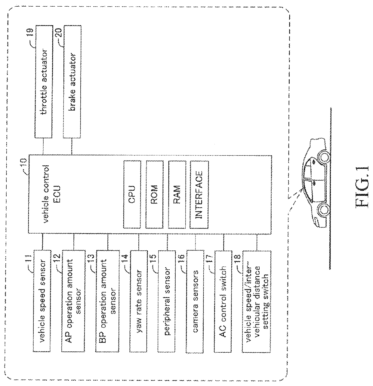
[0086]Hereinafter, a vehicle control apparatus according to a first embodiment of the present invention (hereinafter, also referred to as a “first embodiment apparatus”) will be described, referring to figures. The first embodiment apparatus is applied to a vehicle shown in FIG. 1. As shown in FIG. 1, the first embodiment apparatus comprises a vehicle control ECU 10 (hereinafter, also simply referred to as “ECU 10”).

[0087]ECU is an abbreviation of Electric Control Unit and is an electronic control circuit comprising a microcomputer as a main component parts, the microcomputer including CPU, ROM, RAM, interfaces, and the like. The CPU realize / perform various functions (mentioned later) by executing instructions (i.e. routines) stored in the ROM.

[0088]A specific configuration of the first embodiment apparatus will be described. Following sensors and switches are connected to the ECU 10, the sensors and the switches being a vehicle speed sensor 11, a brake pedal operation amount sensor...

case b

here the Vehicle is Traveling on an Ascending Road by the AC Control

[0133]FIG. 4 is a time chart showing a time transition of each force acting on the vehicle in a case B. The present case assumes a case where the driver operates the brake pedal for a purpose of moderating the acceleration feeling under a situation where the vehicle is traveling on an ascending road during the execution of the AC control. On the vehicle, a gradient force with a negative value is acting. Thus, in the present case, the controlled braking force is maintained as a zero value, and an acceleration control and a deceleration control of the vehicle are executed only with the controlled driving force. Specific description will be made below. It should be noted that in the case A, a description about the operation detail of the first embodiment apparatus common to all cases was made in addition to the operation detail of the first embodiment apparatus unique to the case A. Therefore, in the present case, a de...

case d

here the Vehicle Stops During the Execution of the AC Control

[0149]FIG. 6 is a time chart showing a time transition of each force acting on the vehicle in a case D. The present case assumes a case where the driver operates the brake pedal for a purpose of maintaining or increasing the deceleration feeling under a situation where the second longitudinal force applied on the vehicle by the AC control is decreasing.

(Driving Force Control)

[0150]During the execution of the AC control, the first embodiment apparatus executes the known AC control (that is, a control to increase a magnitude of the controlled braking force (to decrease a value itself), decreasing the controlled driving force) until the brake pedal operation amount with a positive value is first detected (that is, until the timing P1 arrives). After the timing P1, the second embodiment apparatus executes, based on the values of the flags set as described above, the driving force control every time the predetermined calculatio...


PUM


Abstract

When having determined that an operation of a brake operator is initiated at a first timing and the operation amount continues to increase until a second specific timing arrives to become constant at a second timing, vehicle control means which a vehicle control apparatus comprises executes braking force control in such a manner that a time-differential value of controlled braking force during a first period from the second timing to a first terminal timing matches with a time-differential value of controlled braking force at the second specific timing as well as executes driving force control in such a manner that a time-differential value of the controlled driving force during the first period becomes a value less than or equal to a sum of a time-differential value of the controlled driving force at the second specific timing and a time-differential value of operation braking force at the second specific timing.

Description

TECHNICAL FIELD[0001]The present invention relates to a driving force control to automatically apply (add) driving force (controlled driving force) on a vehicle and to a braking force control to automatically apply (add) braking force (controlled braking force) on a vehicle.BACKGROUND ART[0002]A vehicle control apparatus has been conventionally known, the vehicle control apparatus performing, based on a surrounding situation of a vehicle, a driving operation state of the vehicle, a traveling state of the vehicle, and so on, a driving force control to automatically apply driving force on the vehicle and a braking force control to automatically apply braking force on the vehicle. Controls as mentioned above are performed as a driving support control and an automatic driving control. Here, the “surrounding situation of a vehicle” includes information on a distance, a direction (orientation), a relative speed, and the like for an obstacle (an other vehicle, a pedestrian, a building, and...

Claims


Application Information

Patent Timeline
Patent Type & Authority Applications(United States)
IPC IPC(8): B60W30/18B60T7/12B60W20/15B60T8/171
CPCB60W2510/18B60T8/17551B60W30/18109B60T7/12B60W20/15B60T8/171B60W30/143B60W2540/12B60T7/042B60T7/22G01S13/931G01S17/931G01S15/86G01S15/931G01S2013/9324G01S2013/9323G01S2013/93271G01S2013/93274G01S2015/937G01S13/867G01S17/86B60T8/17555B60T2230/04B60T2220/04B60W10/184B60W50/10B60W2710/0672B60W2710/182B60W2720/106B60W10/06
Inventor AKATSUKA, KOSUKE
Owner TOYOTA JIDOSHA KK
Why Eureka
Try Eureka