Buckling-restrained brace with flat energy dissipation element, building and assembly method

Active Publication Date: 2020-01-09
SHANDONG UNIV
View PDF7 Cites 8 Cited by
  • Summary
  • Abstract
  • Description
  • Claims
  • Application Information

AI Technical Summary

Benefits of technology

[0025]Compared with the prior art, in the buckling-restrained brace with the flat energy dissipation element of the present invention, the inner restrained member and the flat energy dissipation element are connected through bolts and thus offer ease of assembly and disassembling, and the postearthquake detection for damage to the flat energy dissipation element and replacement of the damaged flat energy dissipation element. When the buckling-restrained brace with the flat energy dissipation element is installed, the first steel square tube and the second steel square tube of the inner restrain

Problems solved by technology

1) Cumbersome disassembly and replacement: an energy dissipation element of the buckling-restrained brace needs to dissipate energy from an earthquake. The energy dissipation will inevitably cause damage or rupture of the energy-dissipation element, so the energy dissipation-seismic effect of the buckling-restrained brace may be greatly compromised in the aftershocks or subsequent earthquakes. For the existing buckling-restrained brace, in particular to the buckling-restrained brace using mortar or other brittle non-metallic filling material filled in steel tubes to realize a buckling restrained mechanism, after a major earthquake, if the damage to the energy dissipation element needs to be detected, an outer restrained member needs to be disassembled, which is troublesome to operate and can also cause the damage to the brace. Even if special technical means prove that it is necessary to replace the damaged buckling-restrained brace, the removal of the existing buckling-restrained brace and the installation of the new buckling-restrained brace may be onerous for many reasons, for example, limited workspace at the

Method used


Image

  • Buckling-restrained brace with flat energy dissipation element, building and assembly method
  • Buckling-restrained brace with flat energy dissipation element, building and assembly method
  • Buckling-restrained brace with flat energy dissipation element, building and assembly method

Examples


Embodiment Construction

[0043]In order to enable the technical problems, the technical schemes, and the advantages of the present invention to be clearer, the present invention will be described in detail in conjunction with the drawings and the specific embodiments.

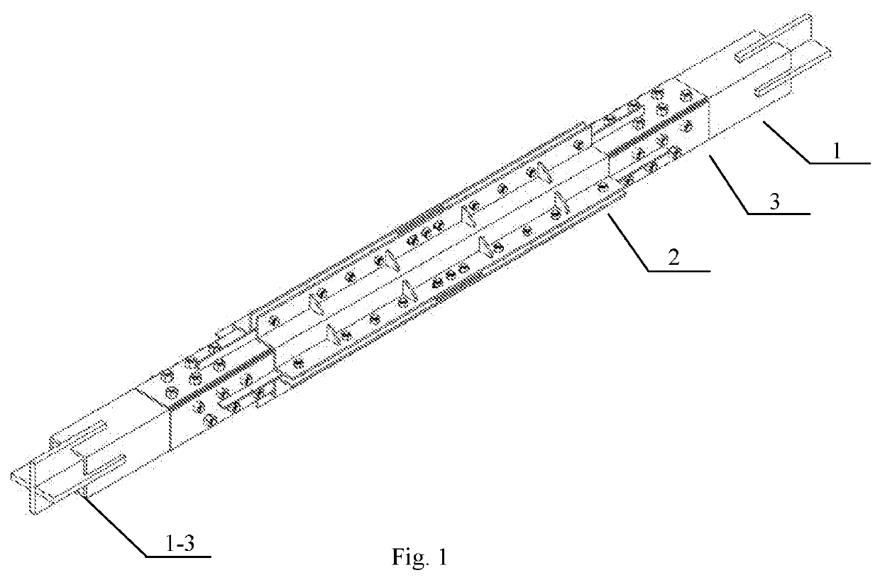
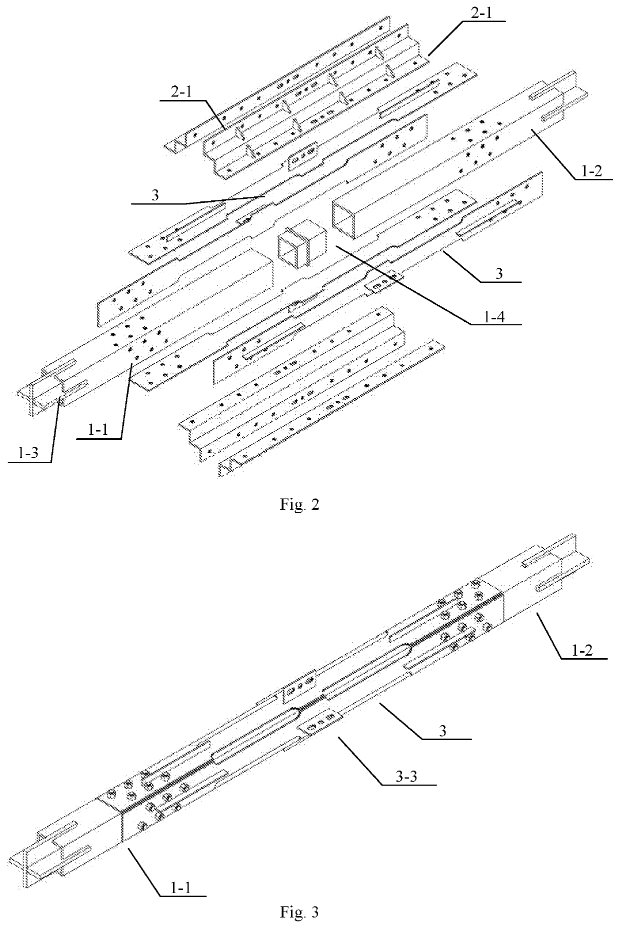
[0044]In one aspect, the present invention discloses a buckling-restrained brace with a flat energy dissipation element, which is used as a brace for a frame, as shown in FIG. 1 to FIG. 16. The buckling-restrained brace comprises a telescopic inner restrained member 1, an outer restrained member 2 sleeved outside the inner restrained member 1, and the flat energy dissipation element between the inner restrained member 1 and the outer restrained member 2, wherein,

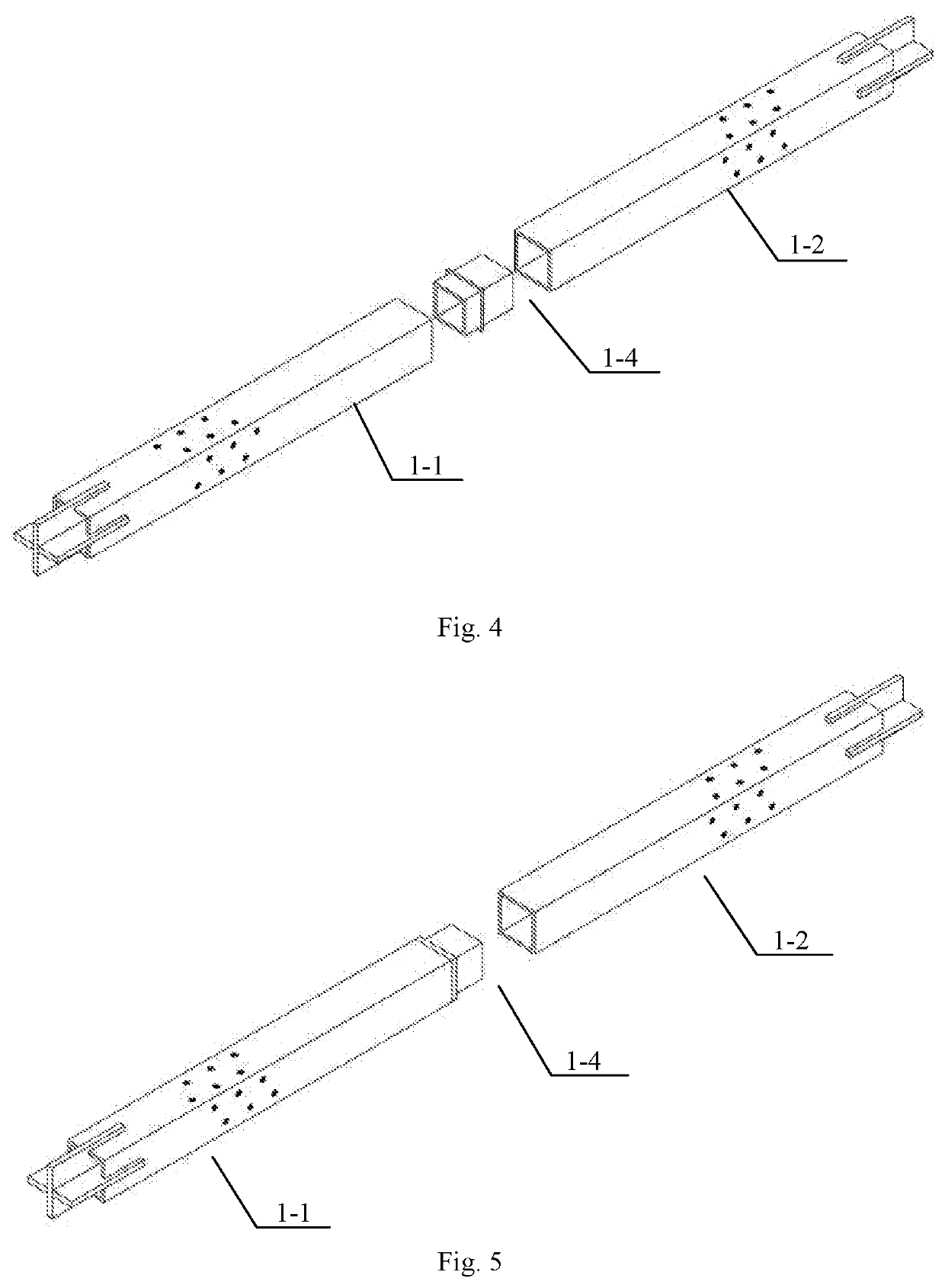
[0045]the inner restrained member 1 comprises a first steel square tube 1-1 and a second steel square tube 1-2 with the same length and outer section, the first steel square tube 1-1 and the second steel square tube 1-2 are connected, the far ends of the first steel square tube 1-1 and ...


PUM


Abstract

A buckling-restrained brace with a flat energy dissipation element, a building with the brace and an assembly method of the brace belongs to the field of force-resisting members of structural engineering. The brace includes a telescopic inner restrained member, an outer restrained member sleeved outside the inner restrained member, and the flat energy dissipation element between the inner and outer restrained members; the inner restrained member includes a first and a second steel square tube which are connected; the flat energy dissipation element includes four flat fuses, and two ends of each fuse are connected to four sides of the first and second steel square tube by bolts; and the inner section of the outer restrained member is square, the outer restrained member covers the flat energy dissipation element, and a certain gap is disposed between the outer restrained member and the flat energy dissipation element.

Description

FIELD OF THE INVENTION[0001]The present invention relates to the technical field of force-resisting members of structural engineering, in particular to a buckling-restrained brace with a flat energy dissipation element, a building and an assembly method.BACKGROUND OF THE INVENTION[0002]In a multistoried or high-rise building steel structure system, a frame is the most basic unit. A brace enables the steel frame to have higher lateral resisting stiffness and strength, so as to reduce the lateral displacement of the frame during earthquake and avoid or reduce the damage to non-structural members. A buckling-restrained brace overcomes the disadvantages of compressive buckling of common braces, and offers enhanced energy absorption capability, reduced difference in tensile and compression resistances and ease of computer modeling.[0003]After the 1994 Northridge Earthquake and the 1995 Kobe Earthquake, the use of buckling-restrained brace substantially increased in new buildings and seis...

Claims


Application Information

Patent Timeline
IPC IPC(8): E04B1/98E04G23/02
CPCE04B2001/2448E04G23/02E04B2001/2415E04G25/04E04H9/024E04B1/98E04B2001/2442
Inventor HOU, HETAOZHANG, SHAOYUANHAN, XIANGDU, ZHIHAOLIU, XIAOFANG
Owner SHANDONG UNIV
Why Eureka
Try Eureka