Centrifugal deaerator for a turbomachine
- Summary
- Abstract
- Description
- Claims
- Application Information
AI Technical Summary
Benefits of technology
Problems solved by technology
Method used
Image
Examples
Embodiment Construction
[0047]In the figures, the scales and proportions are not strictly adhered to and this, for purposes of illustration and clarity.
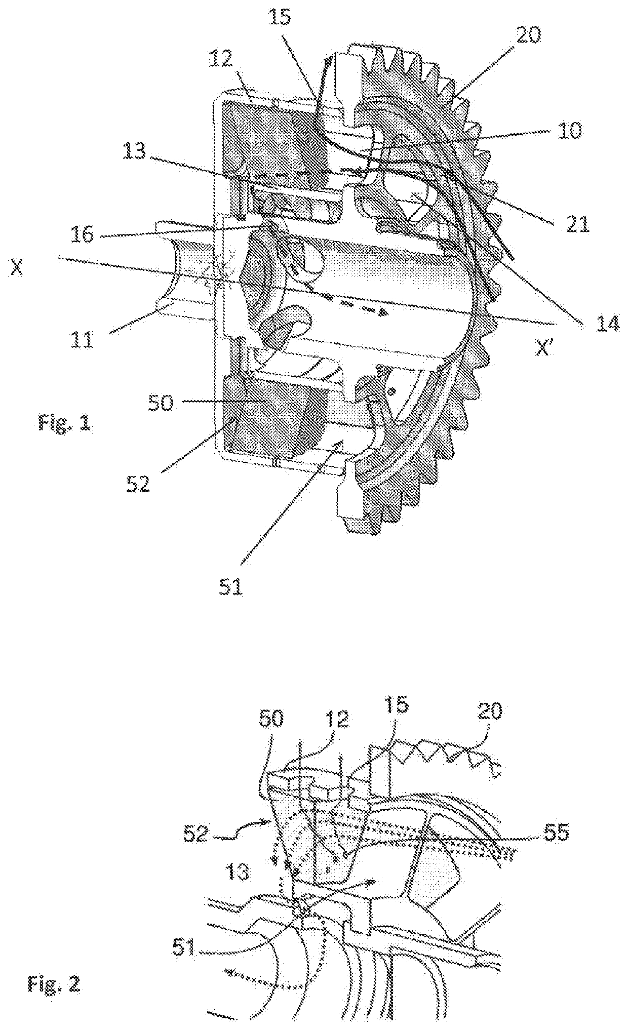
[0048]A deaerator according to the invention comprises, such as represented in FIG. 1, an annular housing 10 for the centrifugal separation of an air / oil mixture arranged around a hollow shaft 11. This annular housing 10 is delimited by an outer annular wall 12 and an inner annular wall 13. This housing 10 comprises a plurality of deaerating compartments distributed around the hollow shaft 11.
[0049]The deaerator further comprises a plurality of axial inlets 14 allowing the air / oil mixture to enter into the housing 10. Each compartment of the housing 10 is connected to an axial inlet 14 such that each compartment can receive a mixture to be separated by a dedicated inlet.
[0050]The deaerator further comprises a plurality of radial oil outlets 15 arranged in the outer wall 12 and configured to be able to evacuate the oil separated from the mixture by the effec...
PUM
| Property | Measurement | Unit |
|---|---|---|
| Thickness | aaaaa | aaaaa |
Abstract
Description
Claims
Application Information
 - R&D Engineer
- R&D Manager
- IP Professional
- Industry Leading Data Capabilities
- Powerful AI technology
- Patent DNA Extraction
Browse by: Latest US Patents, China's latest patents, Technical Efficacy Thesaurus, Application Domain, Technology Topic, Popular Technical Reports.
© 2024 PatSnap. All rights reserved.Legal|Privacy policy|Modern Slavery Act Transparency Statement|Sitemap|About US| Contact US: help@patsnap.com


