Wind turbine

Inactive Publication Date: 2020-01-09
SIEMENS GAMESA RENEWABLE ENERGY AS
View PDF0 Cites 0 Cited by
  • Summary
  • Abstract
  • Description
  • Claims
  • Application Information

AI Technical Summary

Problems solved by technology

This is a very elaborate and expensive way for the maintenance operations.
While this fixation device allows the maintenance operation being performed by only one worker from the inside of the nacelle or the hub, it requires the u

Method used


Image

  • Wind turbine
  • Wind turbine
  • Wind turbine

Examples


Example

[0020]FIG. 2 shows an exploded view of a fixation device according to a first embodiment of the invention;

[0021]FIG. 3 shows a cross sectional view of a fixation area of a facing element to a mounting structure using the fixation device shown in FIG. 2;

Example

[0022]FIG. 4 shows an exploded view of a fixation device of a second embodiment of the invention; and

[0023]FIG. 5 shows a cross sectional view of a fixation area of a facing element to a mounting structure using the fixation device shown in FIG. 4.

DETAILED DESCRIPTION

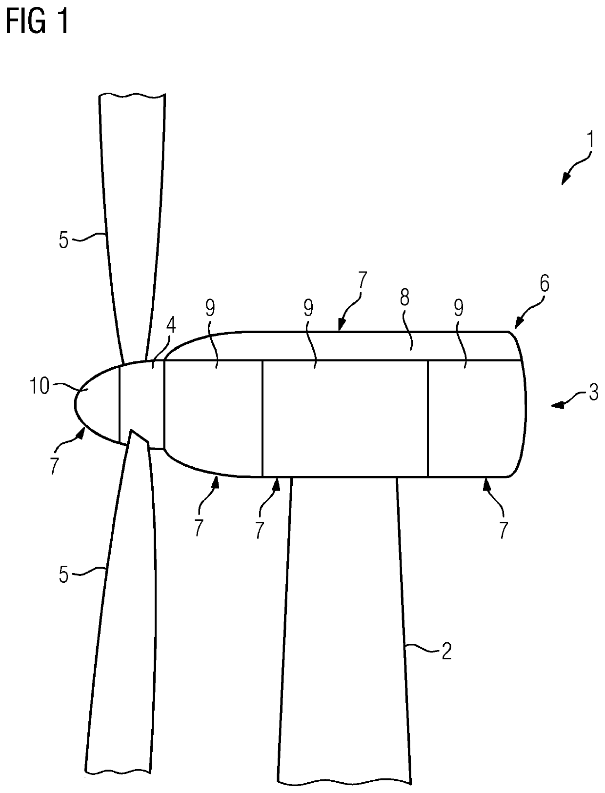
[0024]FIG. 1 shows a wind turbine 1, comprising a tower 2 and a nacelle 3 resting on the tower. It furthermore comprises a hub 4 to which respective rotor blades 5 are attached.

[0025]In this principle sketch the nacelle 3 comprises a housing 6, which comprises several facing elements 7 in the form of a canopy 8 or various wall elements 9, which are attached to a not shown mounting structure of the nacelle 3 used for housing the components in the inner of the nacelle 3.

[0026]Also, the hub 4 is provided with a facing element 7 in the form of a spinner 10 covering the hub 4. Also, this spinner 10 is attached to a respective mounting structure of the hub 4.

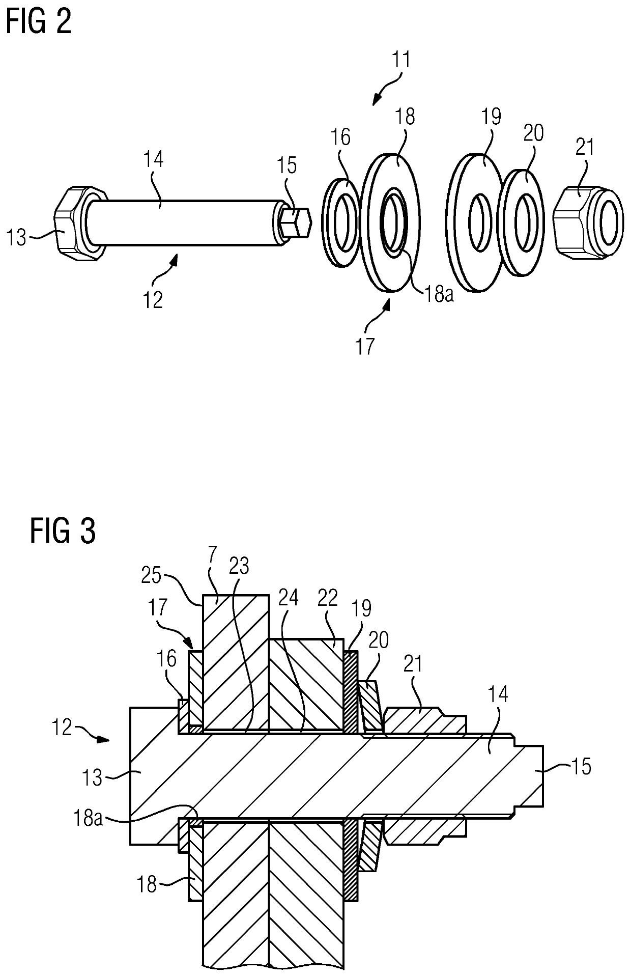
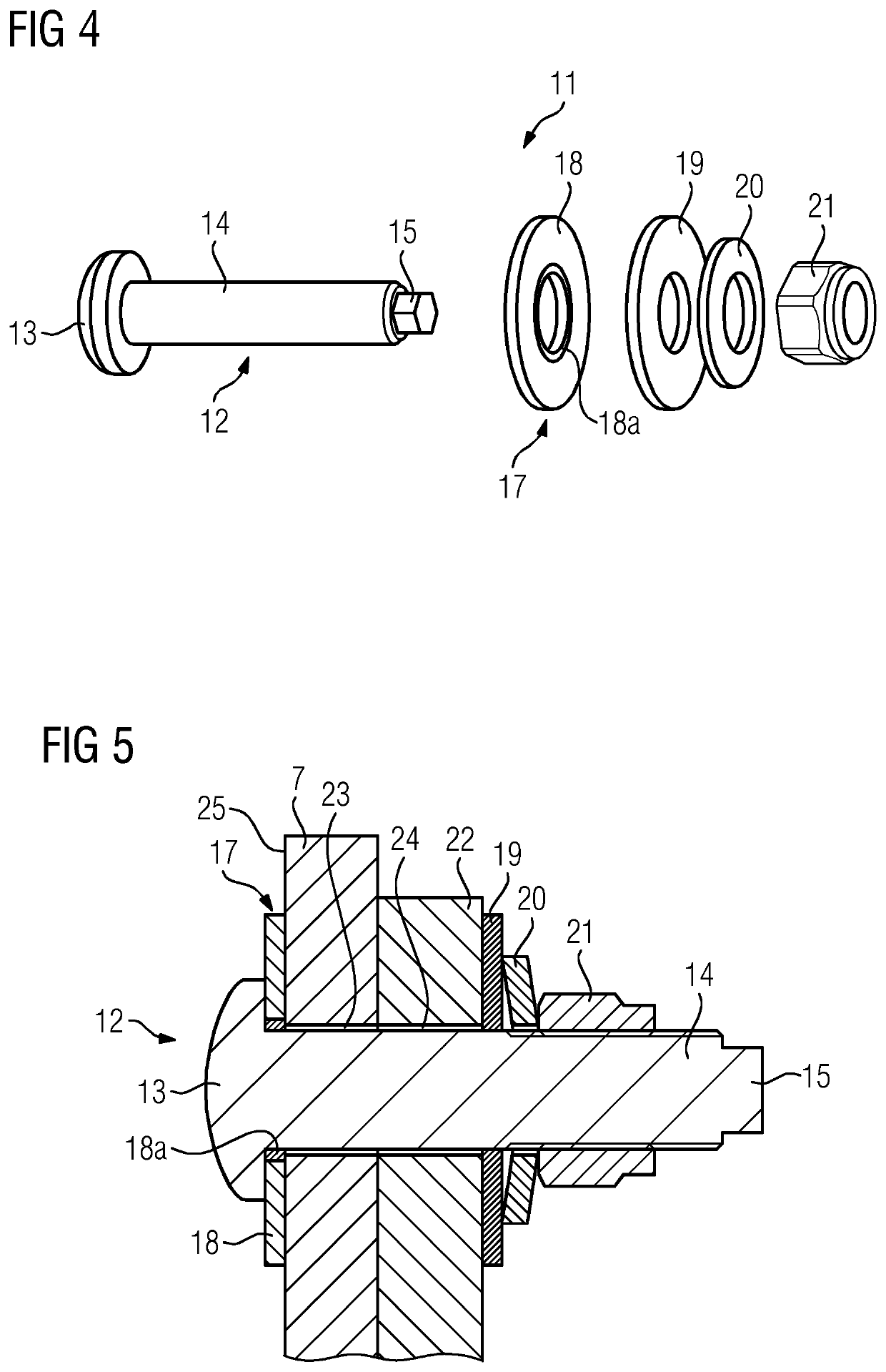
[0027]For attaching the various facing elements 7 to the respective ...


PUM


Abstract

Provided is a wind turbine with a nacelle including a mounting structure to which at least one facing element is attached and/or with a hub including a mounting structure to which at least one facing element is attached, which at least one facing element is attached with several fixation devices, whereby each fixation device includes a bolt with a bolt head at one end, a threaded shaft extending through an opening in the facing element and the mounting structure and a tool mount for attaching a tool for holding the bolt, and a nut screwed on the threaded shaft, with the bolt head positioned at the outside of the nacelle or the hub and the tool mount and nut positioned at the inside of the nacelle or the hub.

Description

CROSS-REFERENCE TO RELATED APPLICATION[0001]This application claims priority to European Application No. 18181441.9, having a filing date of Jul. 3, 2018, the entire contents of which are hereby incorporated by reference.FIELD OF TECHNOLOGY[0002]The following refers to a wind turbine with a nacelle comprising a mounting structure to which at least one facing element is attached and / or with a hub comprising a mounting structure to which at least one facing element is attached, which at least one facing element is attached with several fixation devices.BACKGROUND[0003]Modern wind turbines usually comprise at least one, usually several facing or cladding elements which for example are part of a nacelle comprising the relevant components for producing energy. Such a nacelle facing element is for example a canopy or a side wall segment or the like. Another component which usually comprises such a facing element is the hub, to which a facing element in form of a spinner cover is attached....

Claims


Application Information

Patent Timeline
IPC IPC(8): F16B35/04F03D80/00F16B23/00F16B43/00
CPCF05B2240/14F03D80/00F16B23/0007F16B43/001F16B35/042F05B2260/301F03D80/50F03D13/00F16B5/0266F16B5/0642F16B35/045Y02E10/72
Inventor SVENDSEN, KENNETHLUCAS, THOMAS GEORGERAHN, HENRIK
Owner SIEMENS GAMESA RENEWABLE ENERGY AS
Why Eureka
Try Eureka