
Agricultural work machine

a work machine and work technology, applied in the field of agricultural work machines, can solve the problems of affecting the efficiency of harvesting operations, and requiring time-consuming clearing of crop jams, so as to achieve the effect of further improving the monitoring of crop collection arrangements

Active Publication Date: 2020-01-16
CLAAS SELBSTFAHRENDE ERNTEMASCHINEN GMBH
View PDF0 Cites 25 Cited by
  • Summary
  • Abstract
  • Description
  • Claims
  • Application Information

AI Technical Summary

Benefits of technology

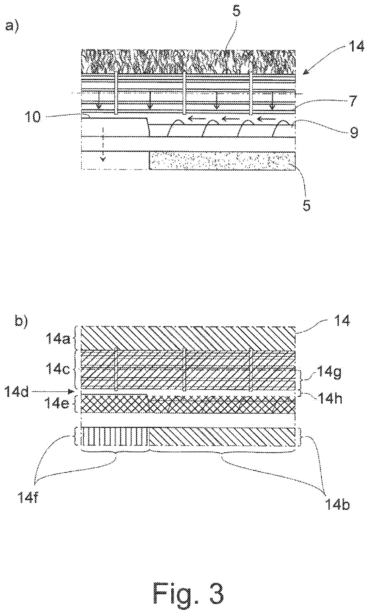
This invention is about improving the monitoring of a crop collection arrangement on an agricultural work machine. The invention involves using an image processing unit to create two maps: a velocity characteristic map and a directional change characteristic map. These maps are then used together or individually by a control device to control processes in the work machine and the crop collection arrangement. This results in improved accuracy, reliability, and timeliness for monitoring the crop flow. The velocity characteristic map is useful for detecting the velocity and positions of machine parts, while the directional change characteristic map helps identify areas of low velocity and determine if they are caused by jammed crops or simply by the movement of machine parts. This prevents false alarms and ensures timely and accurate crop collection.

Problems solved by technology

If a crop jam occurs, i.e., a reduction in the crop flow velocity to the point of stoppage, the harvesting process must be interrupted and a time-consuming clearing of the crop jam must be performed.
The time required for this significantly compromises the efficiency of the harvesting operation.
Detecting a crop jam at the earliest possible moment can be challenging.
By the time a crop jam has become clearly visible, it is often already too late to correct the operation of the crop collection arrangement.

Method used


Image

  • Agricultural work machine
  • Agricultural work machine
  • Agricultural work machine

Examples


Embodiment Construction

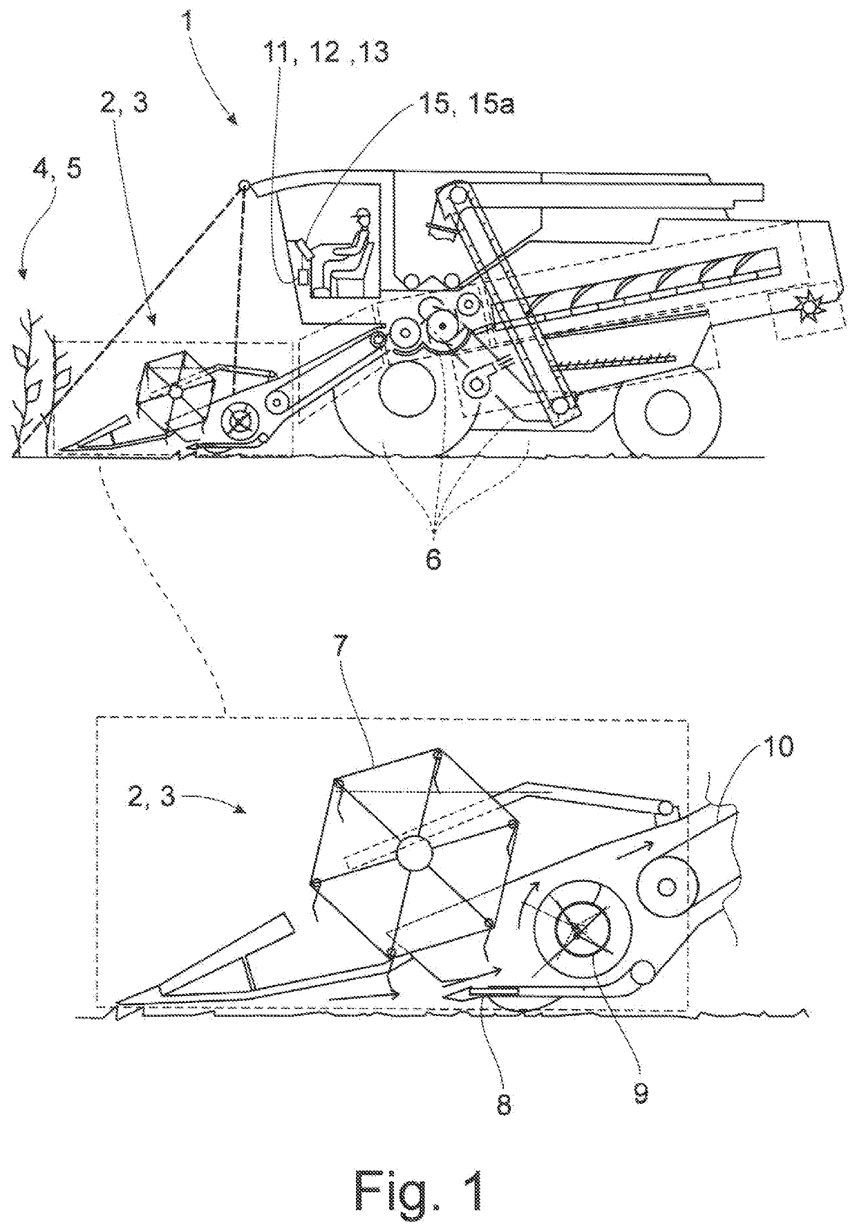
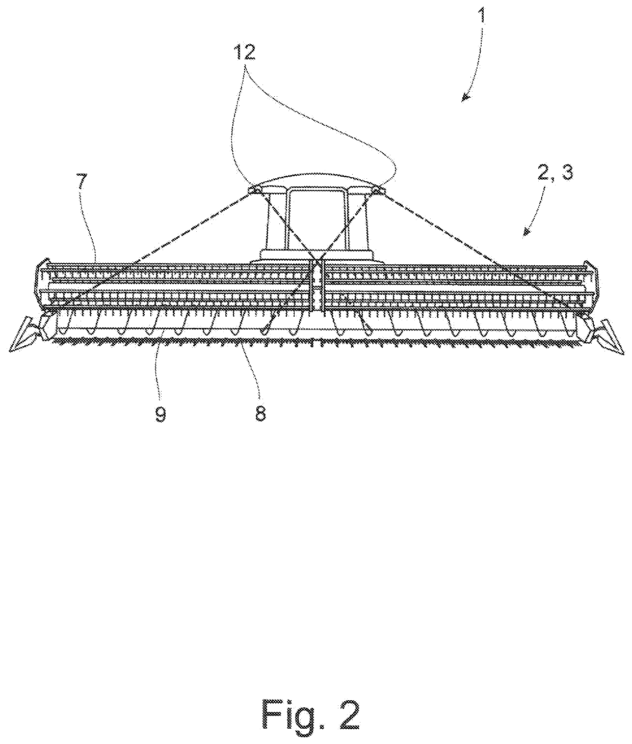
[0025]The proposed agricultural work machine 1 which, in this case, is a combine harvester, for example, has a crop collection arrangement 2 which is formed in this case by a cutting unit 3 and is arranged in front of the agricultural work machine 1 with reference to driving direction. The crop collection arrangement 2 or cutting unit 3 serves to separate and collect crops 4 from field vegetation 5, and the crops 4 are supplied for further processing by a plurality of further work elements 6 of the agricultural work machine 1.

[0026]In this instance and preferably, the crop collection arrangement 2 has, as components, a crop pickup device 7 in the form of a reel, a crop cutting device 8 in the form of a cutting unit table with a knife bar, a crop conveying device 9 in the form of an auger, in particular a cross auger, arranged downstream thereof with respect to the process and a crop intake device 10 in the form of a feed rake which is again arranged downstream thereof with respect t...


PUM


Abstract

An agricultural work machine has a crop collection arrangement for separating and collecting crops from field vegetation, which crop collection arrangement has at least one crop cutting device, a crop conveying device arranged downstream thereof and a crop intake device arranged downstream thereof, and having a control device which has at least one sensor unit for optically detecting a crop flow, an image processing unit for processing images which are generated by the sensor unit based on the optically detected crop flow, and a data output unit for displaying the images processed by the image processing unit. The image processing unit generates a velocity characteristic map and a directional change characteristic map based on the images generated by the sensor unit. The two characteristic maps are utilized jointly or each individually by the control device to control processes in the agricultural work machine and / or in the crop collection arrangement.

Description

CROSS-REFERENCE TO RELATED APPLICATIONS[0001]This application claims priority under 35 USC 119 of German Application No. 10 2018 116990.6, filed on Jul. 13, 2018, the disclosure of which is herein incorporated by reference.BACKGROUND OF THE INVENTION[0002]The invention is directed to an agricultural work machine, in particular a harvester. Agricultural work machines which include, in particular, self-propelled harvesters such as combine harvesters and forage harvesters generally having a crop collection arrangement by which crops in field vegetation can be separated and collected for further processing. A crop collection arrangement in itself generally has a plurality of individual components which can be operated with different parameters. Examples of such components in a combine harvester are a crop pickup device in the form of a reel, a crop cutting device in the form of a cutting unit table with a knife bar, a crop conveying device in the form of an auger, in particular a cross ...

Claims


Application Information

Patent Timeline
Patent Type & Authority Applications(United States)
IPC IPC(8): A01D41/127H04N7/18G06T7/20G06T7/70G06T7/00G06T11/20G06T11/40B60R1/00
CPCH04N7/183G06T7/20G06T7/70B60R2300/30G06T2207/30188B60R2300/20G06T2207/10016G06T11/40B60R1/00A01D41/1271G06T7/97G06T11/20A01D41/127B60R1/24
Inventor BARTHER, MARVINNEITEMEIER, DENNISFISCHER, FRÉDÉRICKETTELHOIT, BORIS
Owner CLAAS SELBSTFAHRENDE ERNTEMASCHINEN GMBH
Learn More