Smart safety helmet with heads-up display

a safety helmet and display technology, applied in the field of smart safety helmets with heads-up displays, can solve the problems of not fully utilizing the existing structure of safety helmets in prior approaches, and achieve the effects of improving safety, improving user safety, and improving safety for fire fighters

Active Publication Date: 2020-01-16
CICCAGLIONE SARAH NICOLE
View PDF8 Cites 10 Cited by
  • Summary
  • Abstract
  • Description
  • Claims
  • Application Information

AI Technical Summary

Benefits of technology

[0003]Therefore, there is a need for apparatus, systems and methods to provide safety systems including a heads-up-display (“HUD”) integrated as an otherwise conventional part of a helmet. Some of these approaches provide apparatus and systems that include a set of sensor packages that are user selectable for quick installation and interchangeability via the exterior of an otherwise conventional helmet structure. Others of these approaches provide a pre-selected set of the sensors in a helmet but allow the user to selectively turn selected sensors on and off depending on the user's application. Some approaches can employ speech recognition systems to provide the user with a hands-free operation of the safety system.
[0004]For snow sports, embodiments include sensors to provide ice detection and blind spot detection. These embodiments can greatly increase user-safety by alerting the user to hazards caused by icy terrain or other users who are in their vicinity but not within the user's line-of-sight.
[0005]Some of these embodiments improve safety for fire fighters by providing an approach with sensors and HUD integrated into an otherwise conventional fire helmet system including a face mask. According to these embodiments, the system provides specialized functionality to alert firefighters of danger in substantially real-time. In some embodiments, location-based notifications are combined with information provided by similarly equipped firefighters at the same site to further improve safety.
[0006]According to one aspect, a safety system is configured to be worn by a user. The safety system includes a helmet, a transparent display screen coupled to the helmet and configured to provide eye safety for the user, the transparent display screen configured to display graphical information to the user in substantially real time. In various embodiments, the graphical information provides feedback to assist the user in safely moving from a first location to a second location within a known environment. The safety system includes an apparatus housed by the helmet. According to some embodiments, the apparatus includes a processor coupled to the transparent display screen, a device coupled to the processor, the device configured to provide information employed to determine a location of the user within the known environment, and at least one sensing system coupled to the processor, the at least one sensing system configured to determine whether the user will be exposed to a hazard should the user move from the first location to the second location via a first route within the known environment. According to one embodiment, if the hazard is identified in the first route, the apparatus communicates an identification of the hazard for display to the user via the transparent display screen. Further, if the hazard is identified in the first route, the apparatus communicates an identification of a second route for display to the user via the transparent display screen, the second route avoiding the hazard with each of the first route and the second route rendered in the transparent display screen. According to various embodiments, the apparatus operates in substantially real time to evaluate conditions in the first route based on information provided by the at least one sensing system to determine whether the hazard exists.
[0007]According to another aspect, a safety system is configured to be worn by a user. The safety system includes a helmet, a transparent display screen coupled to the helmet and configured to provide eye safety for the user, the transparent display screen configured to display graphical information to the user in substantially real time. In various embodiments, the graphical information provides feedback to assist the user in safely moving from a first location to a second location within a known environment. The safety system includes an apparatus housed by the helmet. According to some embodiments, the apparatus includes a processor coupled to the transparent display screen, a device coupled to the processor, the device configured to provide information employed to determine a location of the user within the known environment, and a plurality of sensing systems coupled to the processor, the plurality of sensing systems configured to determine whether the user will be exposed to a hazard should the user move from the first location to the second location via a first route within the known environment. According to some embodiments, the helmet includes a slot configured to receive the plurality of sensing systems. According to one embodiment, if the hazard is identified in the first route, the apparatus communicates an identification of the hazard for display to the user via the transparent display screen. Further, if the hazard is identified in the first route, the apparatus communicates an identification of a second route for display to the user via the transparent display screen, the second route avoiding the hazard with each of the first route and the second route rendered in the transparent display screen. According to various embodiments, the apparatus operates in substantially real time to evaluate conditions in the first route based on information provided by the at least one sensing system to determine whether the hazard exists.

Problems solved by technology

In addition, some of these approaches attempt to fit the system components in the limited amount of space provided in a pair of goggles.
Thus, prior approaches do not fully utilize the existing structure included in safety helmets to make users aware of risks and hazards in their surroundings.

Method used


Image

  • Smart safety helmet with heads-up display
  • Smart safety helmet with heads-up display
  • Smart safety helmet with heads-up display

Examples


Embodiment Construction

[0020]This invention is not limited in its application to the details of construction and the arrangement of components set forth in the following description or illustrated in the drawings. The invention is capable of other embodiments and of being practiced or of being carried out in various ways. Also, the phraseology and terminology used herein is for the purpose of description and should not be regarded as limiting. The use of “including,”“comprising,” or “having,”“containing”, “involving”, and variations thereof herein, is meant to encompass the items listed thereafter and equivalents thereof as well as additional items.

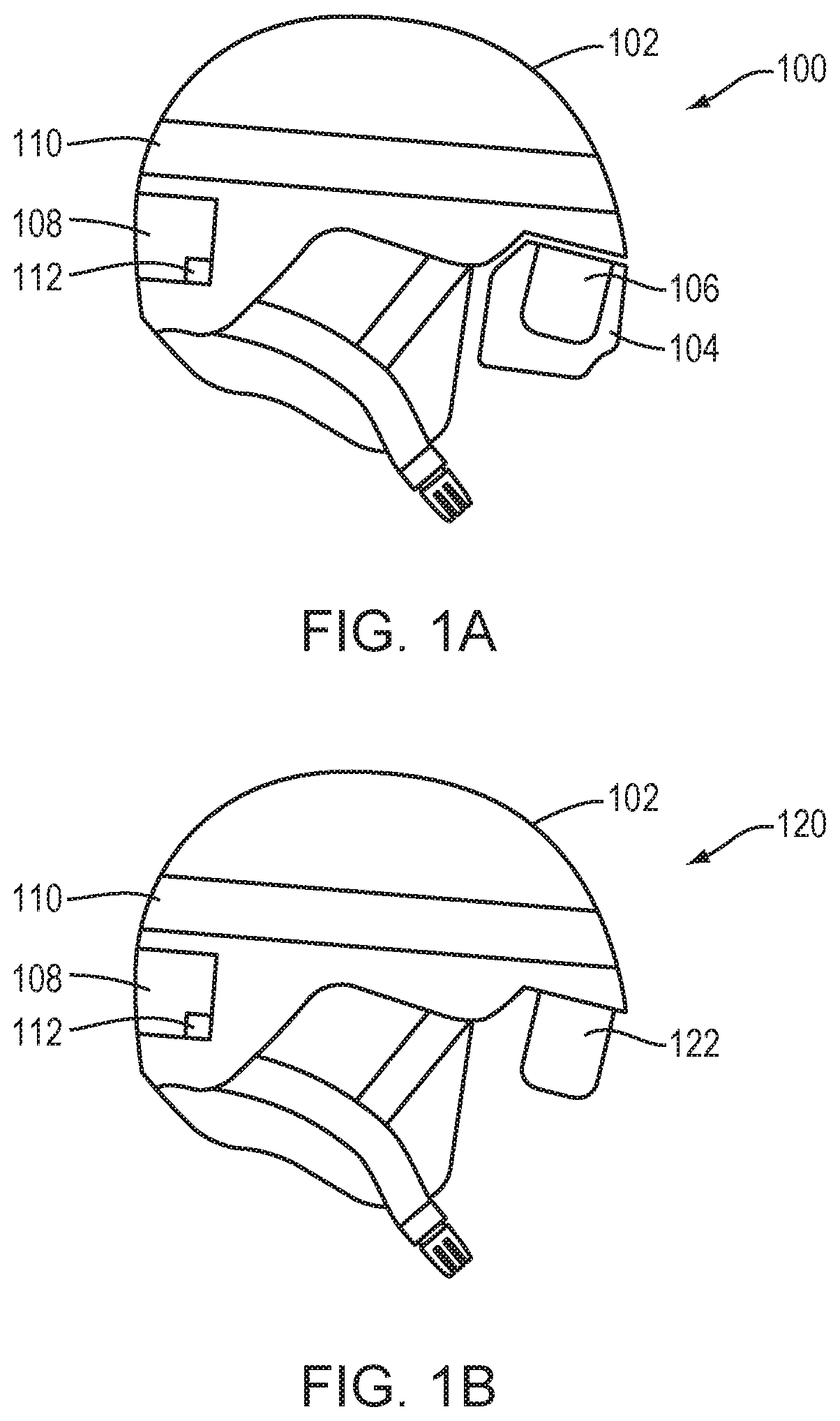
[0021]Referring now to FIG. 1A, a safety system 100 is illustrated in accordance with one embodiment. The safety system 100 includes a helmet 102 and goggles 104 including a display 106. According to the illustrated embodiment, the display 106 is included as a part of the lens of the goggles 104. The helmet 102 includes a compartment 108, a slot 110 and an elec...


PUM


Abstract

A safety system is configured to be worn by a user. The safety system includes a helmet, a transparent display screen coupled to the helmet and configured to provide eye safety for the user, the transparent display screen configured to display graphical information to the user in substantially real time. According to one embodiment, if a hazard is identified in a first route, the apparatus communicates an identification of the hazard for display to the user via the transparent display screen. Further, if the hazard is identified in the first route, the apparatus communicates an identification of a second route for display to the user via the transparent display screen, the second route avoiding the hazard with each of the first route and the second route rendered in the transparent display screen. According to various embodiments, the apparatus operates in substantially real time to evaluate conditions in the first route based on information provided by the at least one sensing system to determine whether the hazard exists.

Description

BACKGROUND OF INVENTION1. Field of Invention[0001]This invention relates generally to apparatus, systems and methods for increasing the safety of individuals who are moving within an environment. More specifically, at least one embodiment, relates to apparatus and systems employing a heads-up-display to provide feedback to the user concerning the environment in substantially real-time.2. Discussion of Related Art[0002]Traditional approaches that employ heads-up-displays generally do so to provide performance feedback, for example, speed, airtime and other performance metrics. In addition, some of these approaches attempt to fit the system components in the limited amount of space provided in a pair of goggles. Others of these approaches include some components in a helmet but require one or more additional components to provide the display. Thus, prior approaches do not fully utilize the existing structure included in safety helmets to make users aware of risks and hazards in their ...

Claims


Application Information

Patent Timeline
Patent Type & Authority Applications(United States)
IPC IPC(8): A42B3/04G06T19/00A42B3/20A42B3/22A42B3/18G02B27/01A61F9/02A61F9/04A62B18/04A62B18/08G01C21/36
CPCA42B3/185A61F9/045G06F3/167A42B3/08A62B18/04G02B27/0172G02B2027/0138A42B3/22A62B18/08G06T19/006G01C21/3697A42B3/20A42B3/046G02B2027/0141A61F9/02G01C21/365A42B3/042A61F9/029G02B27/017G02B2027/0181
Inventor CICCAGLIONE, SARAH NICOLEMOSELEY, ROSS EVANSWALKER, MATTHEW JAMES
Owner CICCAGLIONE SARAH NICOLE
Why Eureka
Try Eureka