
Printing apparatus, printing method, and storage medium

Active Publication Date: 2020-01-16
CANON KK
View PDF0 Cites 5 Cited by
  • Summary
  • Abstract
  • Description
  • Claims
  • Application Information

AI Technical Summary

Benefits of technology

The present invention provides a way to print high-quality images by increasing the coverage of colored portions and enhancing the degree of color development. This is achieved by heating the color development layer for a short time, which results in small colored portions. By increasing the coverage, the degree of color development is improved and the image quality is increased.

Problems solved by technology

However, in particular in a color development layer whose heating time necessary for its color development is limited to a short time, colored portions in the development layer tend to be small in area.

Method used


Image

  • Printing apparatus, printing method, and storage medium
  • Printing apparatus, printing method, and storage medium
  • Printing apparatus, printing method, and storage medium

Examples


first embodiment

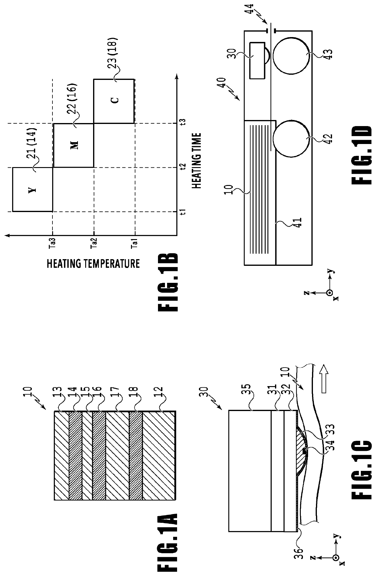
[0046]FIG. 1A is a cross-sectional view of an example of a thermal print medium 10. In the print medium 10 prepared in the present example, image forming layers 14, 16, and 18, spacer layers 15 and 17, and a protection film layer 13 are sequentially laminated on a base material 12 that reflects light. In printing a full-color image in the print medium 10, the image forming layers 14, 16, and 18 are usually yellow (Y), magenta (M), and cyan (C) color development layers. Other image forming layers may be combined.

[0047]The image forming layers 14, 16, and 18 are colorless before sensing heat, and develop their colors by being heated to the respective layer's particular activation temperatures. The order of lamination of the image forming layers 14, 16, and 18 in the print medium 10 can be selected as desired. In the case where the image forming layers 14, 16, and 18 are yellow, magenta, and cyan color development layers, an example of the order of lamination of those layers is the ord...

second embodiment

[0106]FIG. 8 is an explanatory diagram of colored portions in a second embodiment of the present invention. In the present example, the heat generation elements 801 to 806 are driven to generate heat on the basis of heating pulses so as to cause pixel lines 131 to 133 to develop magenta (M) and cause pixel lines 134 to 136 to develop yellow (Y).

[0107]The pixel lines 131 and 132 are caused to develop magenta (M) with the same timing as the pixel line 113 in FIG. 6 in the foregoing embodiment, while the pixel line 133 is caused to develop magenta (M) with the same timing as the pixel line 114 in FIG. 6. Also, the pixel line 134 is caused to develop yellow (Y) with the same timing as the pixel line 115 in FIG. 6, while the pixel lines 135 and 136 are caused to develop yellow (Y) with the same timing as the pixel line 116 in FIG. 6. The heating pulses are set to achieve the color development with these timings. In the present example, image processing similar to the image processing in ...

third embodiment

[0110]In the first embodiment, it is necessary to perform control to associate a plurality of pixels (two pixels in the example mentioned earlier) with each other, as mentioned earlier, so that the drive timing for the group of heat generation elements at the odd numbered positions and the drive timing for the group of heat generation elements at the even numbered positions can be shifted from each other by an approximately half pixel ( 3 / 7 pulse period). In the present embodiment, such control to associate a plurality of pixels is not necessary.

[0111]FIG. 9 is an explanatory diagram of heating pulses in the present embodiment. In FIG. 9, the upper three rows (Yo, Mo, and Co) represent heating pulses to be applied to the heat generation element at any odd numbered position (801, 803, and 805). Also, the lower three rows (Ye, Me, and Ce) represent heating pulses to be applied to the heat generation element at any even numbered position (802, 804, and 806). The heating pulses for the ...


PUM


Abstract

A print medium in which a plurality of color development layers that develop colors to obtain colored portions by being heated are formed at different positions in the thickness direction is conveyed in a first direction. A plurality of heat generation elements that heat the print medium are controlled so as to selectively cause the plurality of color development layers to develop the respective colors. Heating positions on the print medium are controlled such that, in at least one of the color development layers in the print medium, in a case where lines each including a plurality of pixels which are formed by the colored portions and arranged at a predetermined resolution in the first direction are arranged in a second direction, positions of the plurality of pixels are shifted between the lines in the first direction by a distance smaller than an interval corresponding to a resolution.

Description

BACKGROUND OF THE INVENTIONField of the Invention[0001]The present invention relates to a printing apparatus, a printing method, and a storage medium for printing an image by using a thermal print medium.Description of the Related Art[0002]The specification of Japanese Patent No. 4677431 discloses an apparatus that prints an image by using a thermally sensitive print medium including a plurality of color development layers that develop different colors. These color development layers differ from each other in the heating temperature and heating time necessary for the color development. By using these differences to selectively cause the plurality of color development layers to develop their colors, a color image can be printed.SUMMARY OF THE INVENTION[0003]However, in particular in a color development layer whose heating time necessary for its color development is limited to a short time, colored portions in the development layer tend to be small in area. Hence, there is a possibili...

Claims


Application Information

Patent Timeline
IPC IPC(8): B41J2/355B41J2/525
CPCB41J2/525B41J2/355B41J2/32B41J11/0045B41J29/393B41J11/42B41J2/33515B41J11/008B41M5/34B41M5/40
Inventor FUJITA, TAKASHISASAKI, TAKERUOGAWA, HIROAKITSUCHIYA, OKINORIYAMADA, AKITOSHI
Owner CANON KK
Learn More