
Wing panel assembly system and method

Active Publication Date: 2020-01-16
THE BOEING CO
View PDF22 Cites 2 Cited by
  • Summary
  • Abstract
  • Description
  • Claims
  • Application Information

AI Technical Summary

Benefits of technology

The patent describes a way to assemble wing panels for aircraft using a special system. The system has a movable bridge with multiple lifting mechanisms that can hold and move stringers, which are used to reinforce the skin of the wing panel. The method involves using the lifting mechanisms to lift the stringer, moving it to the desired position over the skin of the wing panel, and then releasing it. This process helps to make assembly of wing panels faster and more efficient.

Problems solved by technology

Locating and placing the stringers on the wing skin was traditionally done manually, which was time-consuming and required many man-hours.
Additionally, there may be practical limits to the sizes of the fixtures or jigs.

Method used


Image

  • Wing panel assembly system and method
  • Wing panel assembly system and method
  • Wing panel assembly system and method

Examples


Embodiment Construction

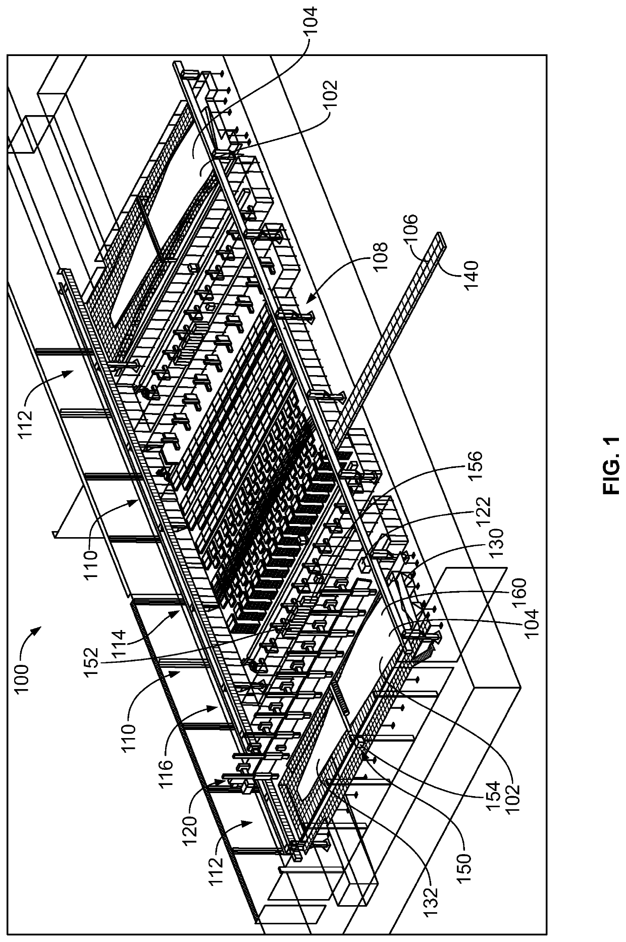
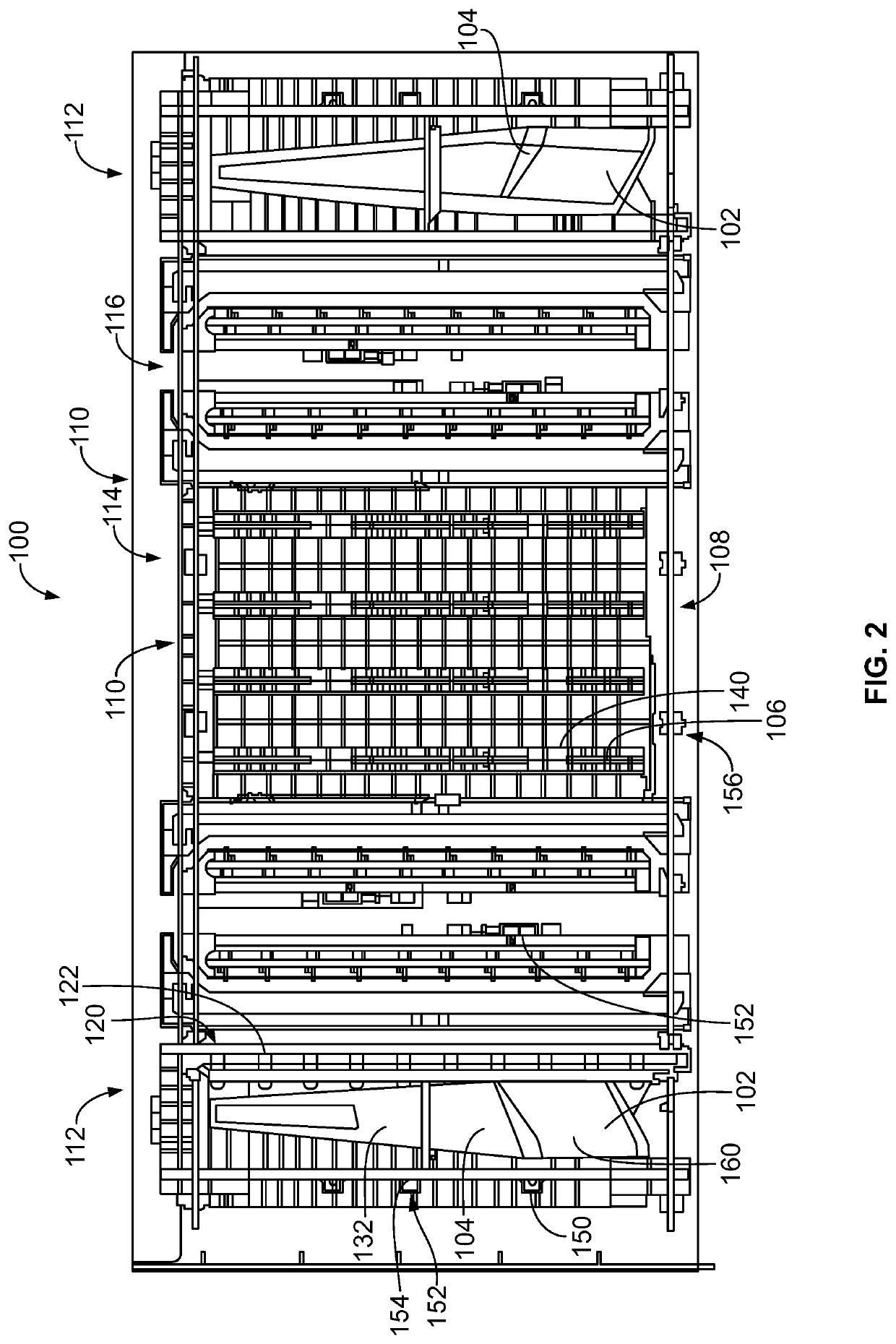
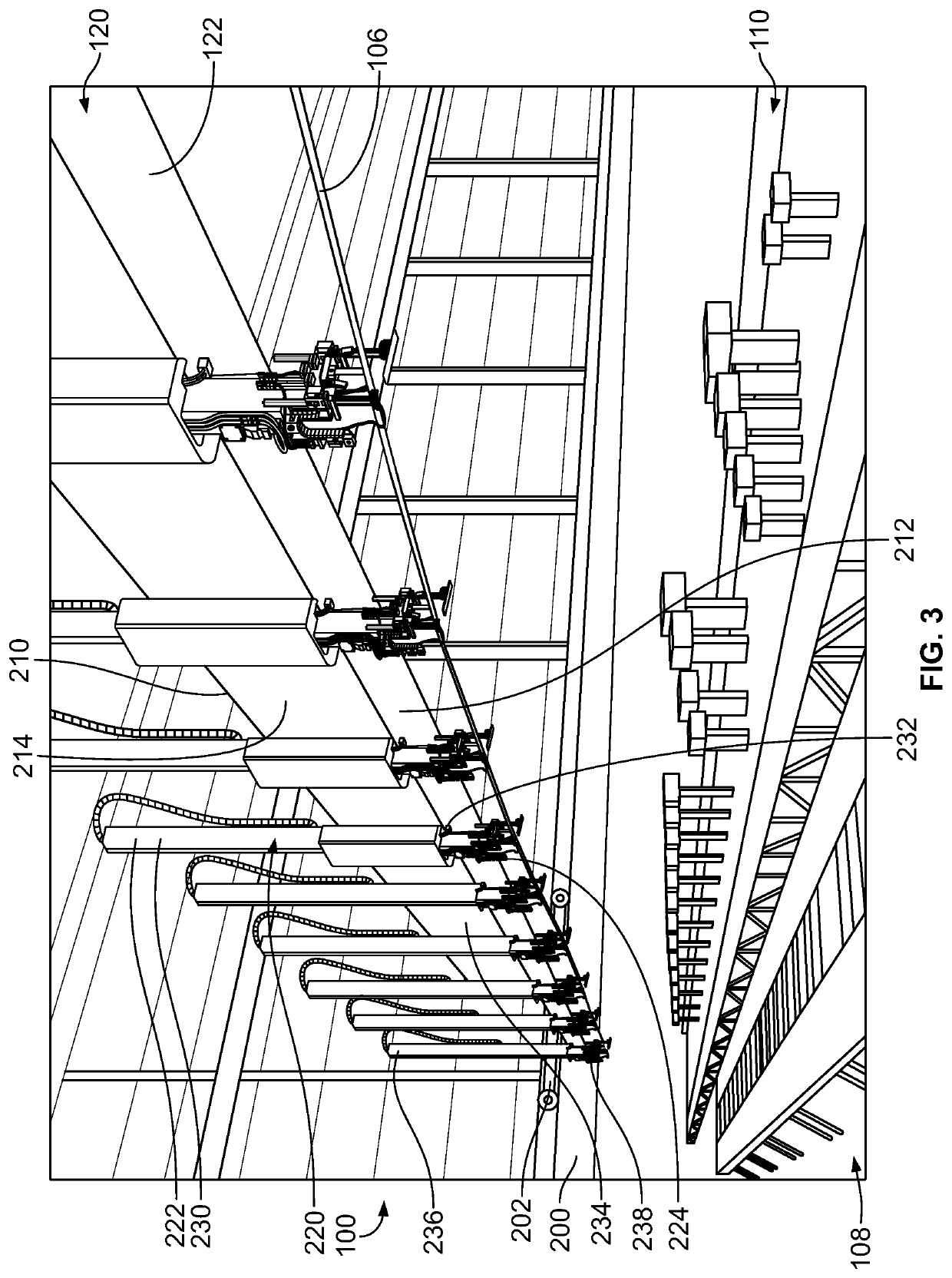
[0012]FIG. 1 is a perspective view of a wing panel assembly system 100 in accordance with an example used to assemble wing panels 102 of an aircraft. FIG. 2 is a top view of the wing panel assembly system 100 in accordance with an example. The wing panel assembly system 100 includes a plurality of sequential operational stations with different manufacturing operations being performed within each station. The stations are arranged in sequence such that components of the wing panel 102, such as a skin 104, a stringer 106, and the like, move between the stations to allow the wing panel 102 to be fabricated. Optionally, wing panels 102 may be manufactured at both sides, such as to manufacture an upper wing panel and a lower wing panel at the same time, which may then be assembled to form a wing box for the aircraft. In an example, the components are generally moved through the assembly process, such as from station to station by an automated material transport system, such as an overhea...


PUM


Abstract

A wing panel assembly system includes a wing build station, a stringer staging station, and an overhead gantry sub-system including stringer lifting assemblies having lifting mechanisms and end effectors. The end effector has a stringer holder engaging and holding a stringer. The end effector has an actuator operable to move the stringer holder in at least one direction relative to the lifting mechanism. Each stringer lifting assembly is configured to move the stringer from the stringer staging station to the wing build station located relative to a surface of a skin of the wing panel to place the stringer onto the skin of the wing panel in a determined location.

Description

BACKGROUND[0001]The subject matter herein relates generally to a wing panel assembly system and method.[0002]In order to manufacture a wing panel for an aircraft, a wing skin is provided and a plurality of stringers are secured to the wing skin. Locating and placing the stringers on the wing skin was traditionally done manually, which was time-consuming and required many man-hours. Some known manufacturing systems have utilized fixtures or jigs to hold and locate the stringers. However, the fixtures or jigs are specific to one particular wing skin design. Additionally, there may be practical limits to the sizes of the fixtures or jigs.[0003]A need remains for a system and method for assembling wing panels in a cost effective and reliable manner.BRIEF DESCRIPTION[0004]In one example, a wing panel assembly system is provided including a wing build station configured to hold a wing panel, a stringer staging station configured to hold a stringer, and an overhead gantry sub-system includ...

Claims


Application Information

Patent Timeline
IPC IPC(8): B64F5/10B25J11/00
CPCB64F5/10B64C3/182B64C3/26B25J11/005B23P21/00B23P2700/01
Inventor WELLER, DENNIS MICHAELWITTENBERG, THOMAS GEETORRES MARTINEZ, MANUEL
Owner THE BOEING CO
Learn More