
Micro Flow-Through Electroporation Devices And Methods Of Cell Transfection

Active Publication Date: 2020-01-16
NANOCAV LLC
View PDF0 Cites 1 Cited by
  • Summary
  • Abstract
  • Description
  • Claims
  • Application Information

AI Technical Summary

Benefits of technology

The patent describes methods and devices for efficiently and successfully electroporation of cells, particularly for large manufacturing processes. This can involve using an electroporation apparatus with a specific design that allows for high efficiency and viability of cells.

Problems solved by technology

Electroporation is commonly used at the laboratory scale (e.g., using small cuvettes with a capacity of about 0.5 mL), but such laboratory based techniques are not suitable for large scale, clinical grade production, due to lack of efficiency and high cost.
Other transfection methods, such as lipid-based techniques using Lipofectamine 2000, are also frequently used, but have similar drawbacks due to high cost.
Additionally, lipid based methods do not work well with some cell types of clinical interest, e.g., NK cells such as haNKs.
While commercial products exist such as Maxcyte for large scale transfection, e.g., reaction sizes of greater than 1 mL, these products are also expensive and / or lack a high-throughput capability.
Similarly, these commercial products are not optimal for transfecting NK cells, often leading to poor yield and / or issues with low cell viability.
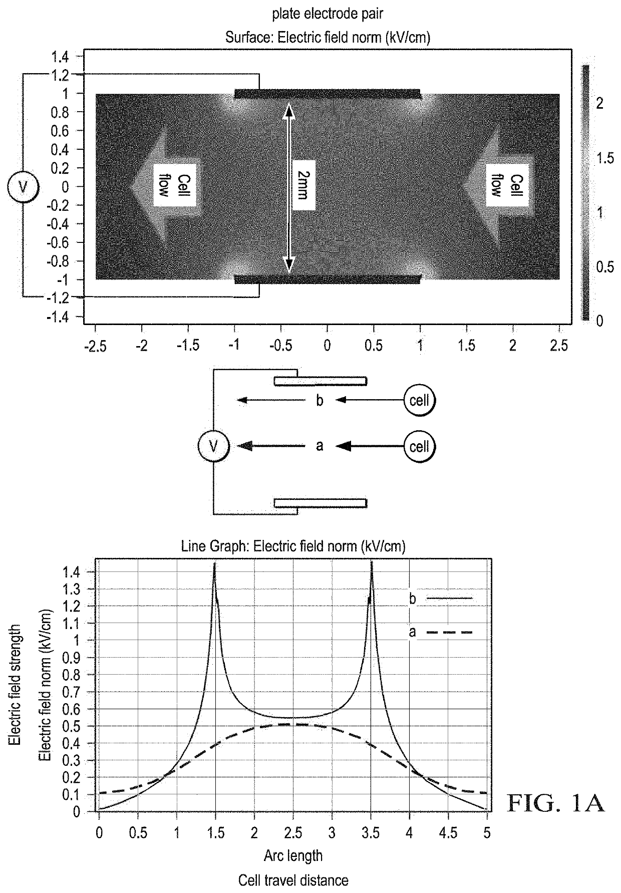
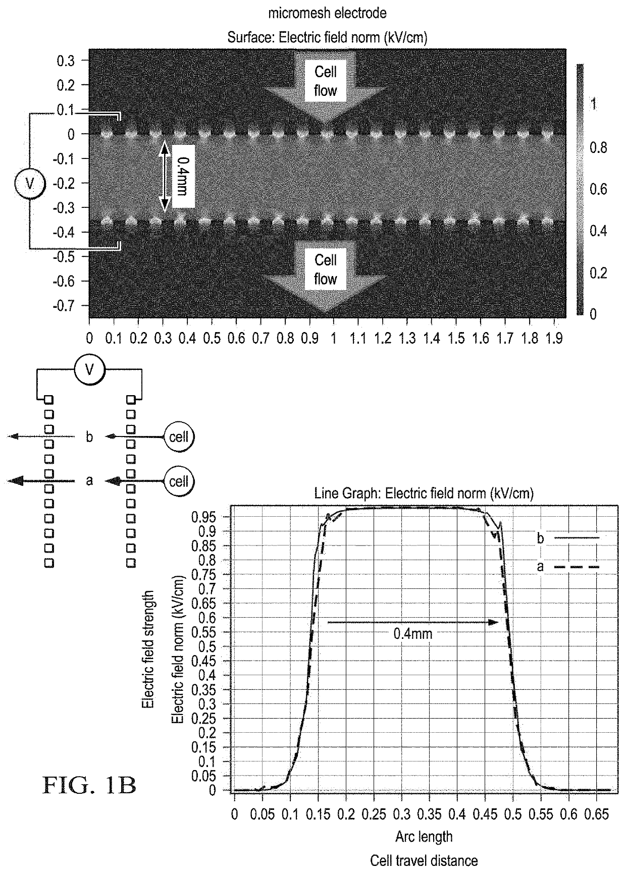
However, the electric field is non-uniform, with cells in the middle of the chamber, shown as (a), experiencing a more uniform electric field while cells near an electrode, shown as (b), experience a non-uniform electric field and in particular, experience an electric field spike present at the boundary of the electrode.
While this technique provides a more uniform electric field than passing between two parallel electrode plates, as shown by the similar trajectories of cells in the middle of the chamber (a) and near the boundary of the chamber (b), the chamber width or distance between the upper micromesh electrode and lower micromesh electrode is limited, leading to a low transfection efficiency.
Even though various transfection systems and methods exist for mammalian cells, such techniques suffer from one or more disadvantages.

Method used


Image

  • Micro Flow-Through Electroporation Devices And Methods Of Cell Transfection
  • Micro Flow-Through Electroporation Devices And Methods Of Cell Transfection
  • Micro Flow-Through Electroporation Devices And Methods Of Cell Transfection

Examples


example 1

ion of haNK Cells

[0128]In some aspects, conditions for the electroporation of haNK cells are shown in Table 2 below

TABLE 2Conditions for Electroporation of haNK CellsEPEPParameterValueParameterValueCargoDextran 500k (dx500k) at 50 ug / ml;Flow Rate4-6.8 millionGFP-mRNA (mRNA) at 50 ug / mLcells / minCell density5 × 106~1 × 10⁷ / mLTotal16 million cellsSampleMediaBTX: 8 mS / m, 0.27 osm / l;Frequency2HzCw100: 0.11 S / m, 0.12 osm / l;RPMI: 1.37 S / m, 0.28 osm / lResistance200Ω - infNo. of3-4 pulses(Rp)Pulses(discharging ormonophasic pulsetrain)Electric Field1-3 kV / cmQavg0.11-0.44mL / minCapacitance10 uF-150 uFSample Size0.45mL(cuvette)DeviceØ5 mm, d = 420 um, Reg;Time10-30msParametersØ5 mm, d = 560 um, Reg;constantØ10 mm, d = 284 um, offset

[0129]FIGS. 6A-E show experimental results of electroporation reactions. FIG. 6A shows a variety of experimental conditions with varying efficiencies and viabilities. Notably, the conditions of 1.5 kv / cm, Rp 1 k, 10 uF using the IOCO electroporation device resulted in ...

example 2

ion of EC7 Cells

[0131]Typical conditions for the electroporation of EC7 cells are show in Table 3 below

TABLE 3Conditions for Electroporation of EC7 CellsEPEPParameterValueParameterValueCargoDextran 500k (dx500k) at 50 ug / ml;Flow Rate4-17.6 millionGFP-mRNA (mRNA) at 50 ug / mL;cells / minGFP-DNA (DNA) at 50 ug / mLCell density5 × 106~4 × 10⁷ / mLTotal16 million cellsSampleMediaBTX: 8 mS / m, 0.27 osm / l;Frequency2HzCw100: 0.11 S / m, 0.12 osm / l;Cw240: 0.2 S / m, 0.24 osm / l;Eppendorf: 0.35 S / m, 0.09 osm / l;waterResistance200Ω to infNo. of3-4 pulses(Rp)Pulses(discharging ormonophasic pulsetrain)Electric Field0.3-3kV / cmQavg0.44mL / minCapacitance10-75uFSample Size0.44-0.45mL(cuvette)DeviceØ5 mm, d = 420 um, Reg;Time5-20msParametersØ5 mm, d = 560 um, Reg;constantØ10 mm, d = 284 um, offset

[0132]FIGS. 8A-D show experimental results of electroporation reactions in EC-7 cells. FIG. 8A shows a variety of experimental conditions with varying efficiencies and viabilities. Notably, the conditions of 1 kv / cm, Rp 2...

example 3

ration of Various Cell Types

[0139]In other aspects, the methods and systems provided herein may be used to transfect a variety of different cell types. For example, up to 108 cells or more can be transfected by the methods and systems provided herein. The methods and systems provided herein may be used to transfect EC7 cells, haNK cells, CHO cells, and T cells. For example, the methods and techniques presented herein may be used to transfect EC7 cells using a flow rate of 0.6 ml / min with a cell concentration of 4×10⁷ cells / ml. In another example, the methods and techniques presented herein may be used to transfect haNK cells using a flow rate of 0.36 ml / min with a cell concentration of 3×10⁷ cells / ml. In yet another example, the methods and techniques provided herein may be used to transfect CHO cells using a flow rate of 0.45 ml / min with a cell concentration of 2.5×10⁷ cells / ml. For T cells, the methods and techniques presented herein may be used to transfect T cells at a flow rate...


PUM

PropertyMeasurementUnit
Timeaaaaaaaaaa
Timeaaaaaaaaaa
Timeaaaaaaaaaa

Abstract

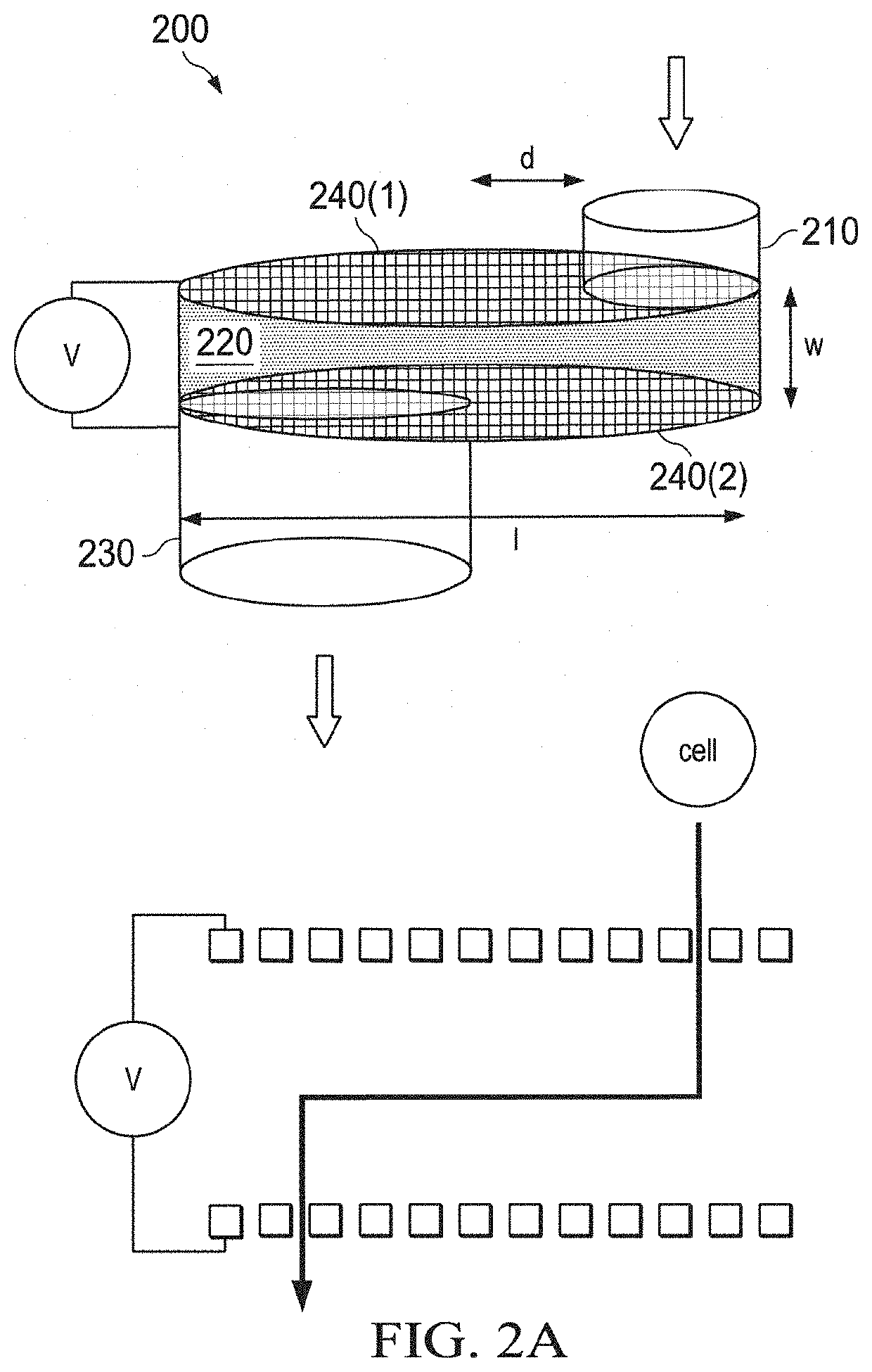
Systems and methods are provided for transfecting cells, such as mammalian cells and nonmammalian cells, using an electroporation apparatus having an electroporation chamber including an upper micromesh electrode, a lower micromesh electrode and a path defined in the electroporation chamber. The electroporation apparatus includes a first input allowing passage of cells into the electroporation chamber and a first output allowing passage of electroporated cells from the electroporation chamber. The first input and the first output are separated by an offset distance.

Description

CROSS REFERENCE TO RELATED APPLICATIONS[0001]This application claims priority under 35 U.S.C. § 119(e) from U.S. Provisional Patent Application Ser. No. 62 / 695,436, filed Jul. 9, 2018, the entire contents of which are hereby incorporated by referenceFIELD OF THE INVENTION[0002]The field of the invention relates to transfection systems and methods, and in particular, electroporation systems and methods.BACKGROUND OF THE INVENTION[0003]The background description includes information that may be useful in understanding the methods and techniques presented herein. It is not an admission that any of the information provided herein is prior art or relevant to the subject matter presented herein, or that any publication specifically or implicitly referenced is prior art.[0004]Transfection may be used to introduce nucleic acids into cells to produce genetically modified cells. Various physical, chemical and viral methods exist for transfecting cells, including optoperforation, polymer based...

Claims


Application Information

Patent Timeline
IPC IPC(8): C12N13/00C12N15/87
CPCC12N13/00C12N15/87C12M35/02C12M23/16A61N1/327C12N15/90
Inventor CHANG, CHIH-WEI
Owner NANOCAV LLC
Learn More