Irregular rock sample high-pressure permeation device with adjustable flow direction and test method thereof

a technology of high-pressure permeation device and irregular rock, which is applied in the field of irregular rock, can solve the problems of difficult to meet the requirements, difficult to objectively obtain the spatial variability of hydraulic parameters of key geological structures, and difficult problems to be solved in front of scientific researchers, so as to shorten the time consumption of the bottom jaw and eliminate vibration

Active Publication Date: 2020-01-16
SOUTHWEST PETROLEUM UNIV
View PDF0 Cites 38 Cited by
  • Summary
  • Abstract
  • Description
  • Claims
  • Application Information

AI Technical Summary

Benefits of technology

[0040]2. The present invention has a propulsion cylinder corresponding to the propulsion shell on the internal wall of a fixing plate, which means a telescopic frequency of the output end of the propulsion cylinder is the same as the amplitude variation frequency generated by the eccentric wheel, wherein when the eccentric wheel generates a vertical upward amplitude, the output end of the propulsion cylinder moves downward to bring a pressure plate into contact with the top surface of the propulsion shell to eliminate vibration in the direction, thereby ensuring stability of the moving process of the shell and the bottom plate, and shortening a time consumption of a bottom jaw to convert from an initial state to a final state.
[0041]3. The present invention drills a limit slot on a sidewall of the sliding plate facing the sliding groove, and the size of the limit slot matches the bottom jaw. After a reinforcing cage is completely lowered to a pile hole, the bottom jaw is moved by a follower plate and turned down to the limit slot, which means the bottom jaw is completely out of contact with a hoop stirrup, and a hook is lifted to make a hanging rib gradually get out of the pile hole, thereby effectively avoiding any interference of the hoop stirrup on the smooth exit of an entire cylindrical frame from the pile hole.

Problems solved by technology

In the prior art, because the laboratory seepage test link is extremely demanding on the sealing of the non-permeable boundaries of the rock sample, the conventional in-door seepage test instrument is only suitable for cylindrical regular sample test (which is convenient to blocking and the technique is developed), or irregular sample test (using cured colloid to seal non-permeable boundary to permanently and efficiently block water) with a fixed flow direction (because the colloidal seal is irreversible, and the direction of seepage and permeation is irreversible).
It is unable to meet the requirements of water conductivity difference analysis under different seepage pathways, and it is difficult to objectively obtain the spatial variability of hydraulic parameters of key geological structures.
Therefore, how to effectively realize the reversible sealing of irregular boundaries, how to freely convert the sealing state (sealed or permeable) of large-scale boundaries, and how to accurately adjust the stress conditions of the seepage environment for large-scale irregular rock samples from the site containing rich geological structure information, are difficult problems to be solved in front of scientific researchers.

Method used


Image

  • Irregular rock sample high-pressure permeation device with adjustable flow direction and test method thereof
  • Irregular rock sample high-pressure permeation device with adjustable flow direction and test method thereof
  • Irregular rock sample high-pressure permeation device with adjustable flow direction and test method thereof

Examples


embodiment 1

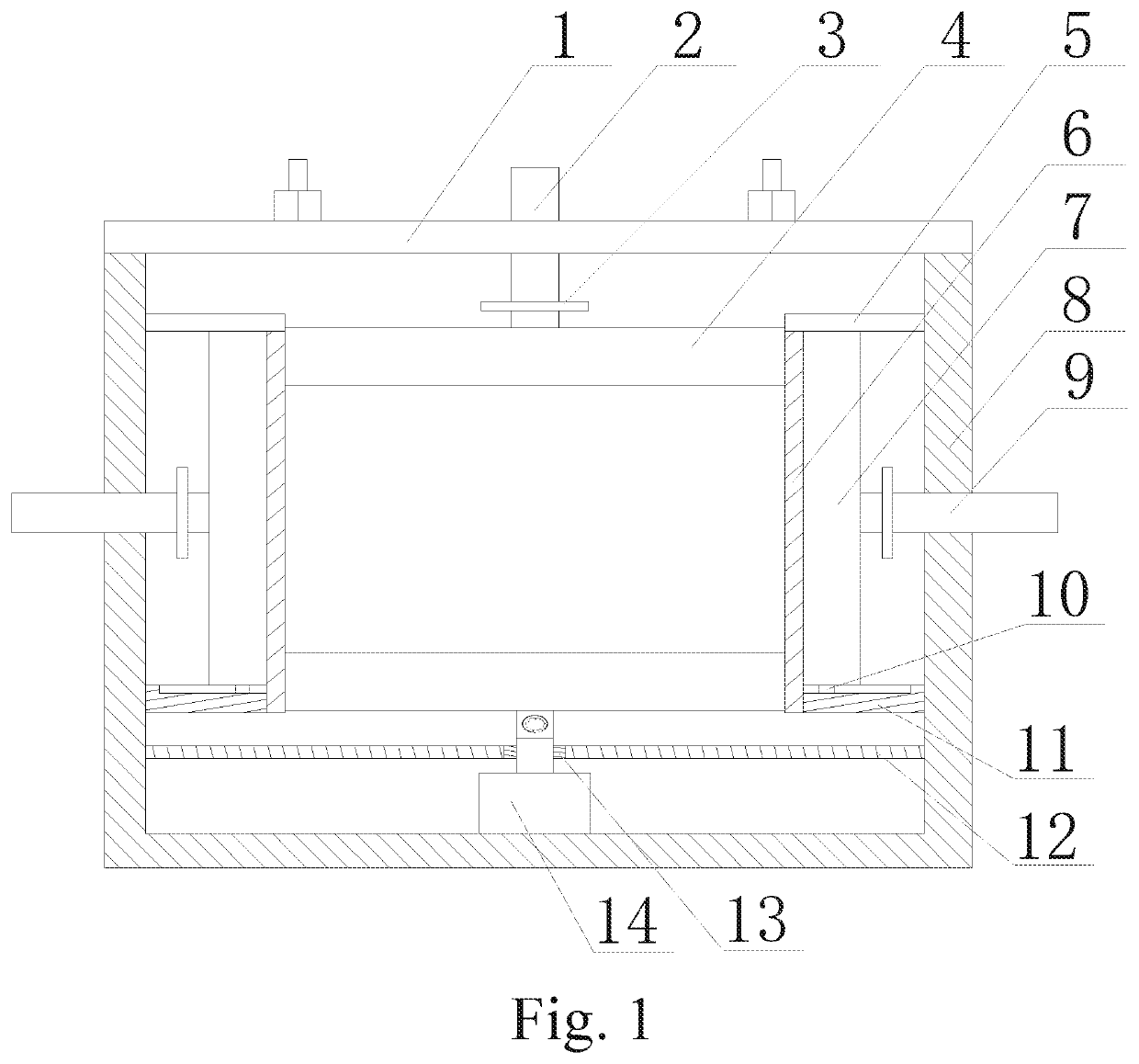
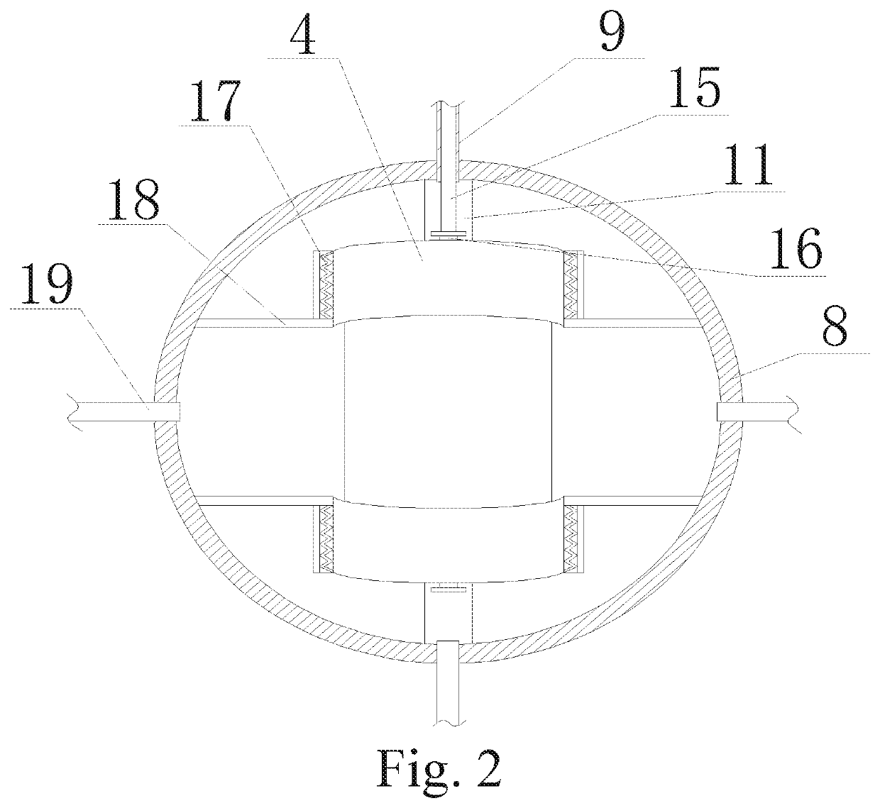
[0056]Referring to FIGS. 1-10, the embodiment 1 comprises: a cylinder body 8 having a top opening, and a sealing cover 1 matched with the top opening of the cylinder body 8, wherein two blocking mechanisms I 7 are symmetrically arranged in the cylinder body 8 along an axis thereof, and two blocking mechanisms II 4 are respectively arranged at an internal top end and an internal bottom end of the cylinder body 8; partitioning plates 6, whose bottom ends are connected to a bottom of the cylinder body 8, are respectively arranged on both sides of each of the blocking mechanisms I 7; one end of a sealing organ cover 17 is connected to a sidewall of each of the partitioning plates 6, and the other end of the sealing organ cover 17 is connect a sidewall of each of the blocking mechanisms I 7; water blocking plates 18 are respectively arranged at both sides of each of the blocking mechanisms I 7 and are perpendicular to the partitioning plates 6; one end of each of the water blocking plate...

embodiment 2

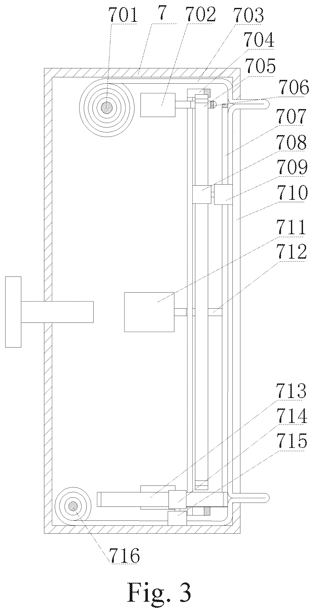
[0064]Referring to FIGS. 1-10, based on the embodiment 1, a pressing frame I 707 is disposed on the output end of the driving cylinder 711 inside the shell, and the pressing frame I 707 is a rectangular bracket formed by splicing four L-shaped plates 24; a telescopic cylinder 26 is mounted on one end surface of each of the L-shaped plates 24, and a connecting rod 27 is fixed on the other end surface; among adjacent L-shaped plates 24, an output end of the telescopic cylinder 26 of one L-shaped plate 24 is connected to the connecting rod 27 of the other L-shaped plate 24; a supporting rod 28 is respectively mounted on a sidewall of each of the L-shaped plates 24, and the supporting rod 28 is connected to the output end of the driving cylinder 711; a pressing frame II 23 is disposed on the output end of the driving cylinder 711 inside the tank, and the pressing frame II 23 is a U-shaped bracket formed by splicing two symmetrically distributed L-shaped plates 24; the telescopic cylinde...

embodiment 3

[0067]Referring to FIGS. 1-10, a function of the first chuck 709 is to move the water blocking film 703 along a fixed track in a lateral direction or a longitudinal direction, and since the water blocking film 703 belongs to a flexible material, the first chuck 709 should provide sufficient clamping force while ensures accurate clamping or releasing of the water blocking film 703. Therefore, the applicant sets the U-shaped body and the two flexible splints 718. In an initial state, the two flexible splints 718 are in contact with each other, and the torsion spring 719 is in a free state. When the first chuck 709 needs to be contacted to hold the water blocking film 703, the electromagnets 717 on the two flexible splints 718 are simultaneously energized to have same magnetic poles, wherein repulsive force is generated between the two electromagnets 717, so that the flexible splints 718 press and compress the torsion spring 719, and an interval between the two flexible splints 718 is ...


PUM

PropertyMeasurementUnit
confining pressuresaaaaaaaaaa
volumeaaaaaaaaaa
osmotic pressureaaaaaaaaaa

Abstract

An irregular rock sample high-pressure permeation device with an adjustable flow direction and a test method thereof are provided, wherein two blocking mechanisms I and two blocking mechanisms II are arranged inside a cylinder body; partitioning plates are respectively arranged on both sides of each of the blocking mechanisms I; water blocking plates are respectively arranged at both sides of each of the blocking mechanisms I; one end of each of the water blocking plates is connected to the sidewall of each of the partitioning plates, and the other end of each of the water blocking plates is connected to an internal portion of the cylinder body; a water injection pipe is disposed between the water blocking plates on a same side. The present invention combines flexible film amorphous close fit properties and easy charging and discharging of free gas.

Description

CROSS REFERENCE OF RELATED APPLICATION[0001]The present invention claims priority under 35 U.S.C. 119(a-d) to CN 201910712083.X, filed Aug. 2, 2019.BACKGROUND OF THE PRESENT INVENTIONField of Invention[0002]The present invention relates to the characterization and evaluation of groundwater flow characteristics for key water-conducting geological structures in engineering rock masses such as rock slopes and mountain tunnels, and more particularly to an in-door high-pressure seepage device for comprehensively characterizing hydrogeological properties of water-conducting structures by quantitatively measuring permeability parameters of an intersecting fracture network in an irregular rock sample. The present invention provides an effective means for analyzing groundwater flow characteristics of regional rock masses in laboratory, and is also a useful exploration for difference analysis of water conductivity of geological structures under different seepage pathways, which provides a new...

Claims


Application Information

Patent Timeline
Patent Type & Authority Applications(United States)
IPC IPC(8): G01N15/08G01N33/18
CPCG01N33/18G01N33/24G01N15/082G01N15/0806G01N15/0826
Inventor GUO, LIANGZHANG, JUNWEIXIAO, ZIWEIWANG, BAOQUANLIAO, MINGWEIQIAN, DELIANGPEI, CHUNJI, YOUJUNZHU, JIAOGUO, HUILIU, ZHUANGZHI
Owner SOUTHWEST PETROLEUM UNIV
Why Eureka
Try Eureka