Method and device for scanning a solid angle

a solid angle and scanning technology, applied in the direction of surveying, navigation, distance measurement, etc., can solve the problems of evaluating further measured quantities based on the pulse shape of the beam like, the shape of the reception pulse may become distorted, and the detection of rapid saturation

Active Publication Date: 2020-01-16
ROBERT BOSCH GMBH
View PDF3 Cites 1 Cited by
  • Summary
  • Abstract
  • Description
  • Claims
  • Application Information

AI Technical Summary

Benefits of technology

[0004]An object of the present invention may be seen in providing a LIDAR device and a method which, in spite of a great range, are also able to register objects in a close range without oversaturation of a detector.
[0007]According to one exemplary embodiment of the method, the energy of the at least one second electromagnetic beam is selected to be below a saturation of at least one detector. Thus, the at least one second beam may be prevented from causing saturation of the detector. Whereas in the case of the at least one first high-energy beam, the danger of saturation of the detector is high, especially in the case of close objects, nevertheless, owing to the at least one second beam, a meaningful measurement of the scanning range may be ensured.
[0010]According to another exemplary embodiment, a ratio of intensity between the at least one first electromagnetic beam and the at least one second electromagnetic beam is varied. Consequently, the generated beams may be adapted flexibly and in situ to a situation. For instance, in the case of an automotive application in a heavily frequented neighborhood, a low ratio of intensity may be used, so that a close range may be scanned more effectively. On the other hand, on a turnpike, the largest possible ratio of intensity could be set between the two beams, so that a corresponding LIDAR device has the greatest range possible, and thus may also be used at higher speeds.
[0011]According to another exemplary embodiment of the method, the delay time between the at least one first electromagnetic beam and the at least one second electromagnetic beam is varied. In doing so, the delay time may be adapted particularly to a distance of the object from the LIDAR device, or at least to a beam source for generating at least one beam. With increasing distance, a generated beam requires more time to travel the distance to the object and back to the detector.
[0016]According to one exemplary embodiment, a variable delay time is implemented between the at least one first generated beam and the at least one second generated beam. Depending on the detector, a recovery time must be taken into account after the saturation. The delay time is thus able to ensure that the at least one second beam may be detected normally by the detector. Negative effects of a saturated detector may thereby be circumvented. Since the at least two beams have the same time base and may be sorted into the same histogram, no additional memory is necessary in the LIDAR device.

Problems solved by technology

Because of the limited dynamic range of customary detectors, when beams are reflected at closer objects, the detectors quickly reach saturation.
Consequently, the shape of the reception pulse may become distorted.
In particular, an evaluation of further measured quantities based on a pulse shape of the beam like, for example, intensity, reflectivity, weather conditions, angle of the target relative to the LIDAR device and the like, may no longer be possible due to the saturation of the detector.

Method used


Image

  • Method and device for scanning a solid angle
  • Method and device for scanning a solid angle
  • Method and device for scanning a solid angle

Examples


Embodiment Construction

[0025]In the figures, the same structural elements in each case have the same reference numerals.

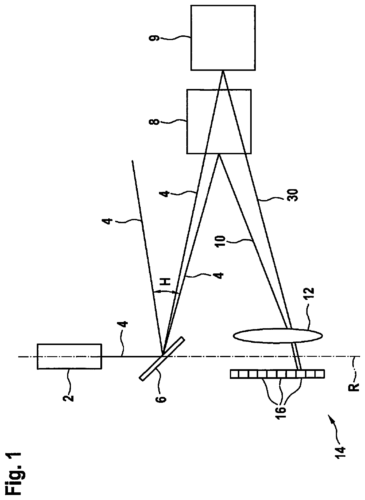
[0026]FIG. 1 shows a first exemplary embodiment of a LIDAR device 1. LIDAR device 1 has a beam source 2 for generating at least one electromagnetic beam 4. Beam source 2 according to the example is a laser 2 which generates beams 4 in a pulse shape. According to the exemplary embodiment, laser 2 is used to generate a beam 4 with a wavelength in the non-visible infrared range. For instance, the wavelength may be greater than 800 nm. Beam 4 generated by laser 2 is deflected by a deflection unit 6 or a rotatable mirror 6. In this case, mirror 6 is pivotable along an axis of rotation R. Thus, mirror 6 is able to deflect generated beam 4 along a defined scan angle H. In addition, mirror 6 is pivotable orthogonally to horizontal scan angle H, and therefore covers a vertical scan angle V. Consequently, LIDAR device 1 is able to scan a solid angle W=V×H and locate possible objects 8, 9 positione...


PUM


Abstract

A method for scanning a scan angle, in which at least one electromagnetic beam is generated, the at least one electromagnetic beam is deflected along the scan angle, and the at least one electromagnetic beam, reflected at an object, is received and detected, wherein after at least one first electromagnetic beam, at least one second electromagnetic beam is generated and the second electromagnetic beam is generated with a lower energy than the first electromagnetic beam. A LIDAR device is also disclosed.

Description

FIELD OF THE INVENTION[0001]The present invention relates to a method for scanning a scan angle as well as a LIDAR device for scanning a scan angle.BACKGROUND INFORMATION[0002]Conventional LIDAR (Light Detection And Ranging) devices are pulsed direct time-of-flight systems which measure the time between emission and reception of a short, high-energy beam pulse or laser pulse. By knowing the velocity of light, a distance between an object and the LIDAR device may subsequently be ascertained based on the time or transit time of the beam.[0003]Avalanche photodiodes or single photon avalanche diodes are usually used as detectors for receiving reflected beams. In order to scan or measure the largest possible ranges of 100-200 m accompanied at the same time by poor reflectivity of an object of less than 10%, within the limits of the eye-safety guideline, the necessary laser pulses may reach peak powers in the kilowatt range, depending on the system configuration. Because of the limited dy...

Claims


Application Information

Patent Timeline
Patent Type & Authority Applications(United States)
IPC IPC(8): G01S17/89G01C3/08
CPCG01C3/08G01S7/4868G01S7/484G01S17/89
Inventor SCHNITZER, REINERHIPP, TOBIAS
Owner ROBERT BOSCH GMBH
Why Eureka
Try Eureka