
Swallowing sensor

a sensor and swallowing technology, applied in the field of swallowing sensors, can solve the problems of increasing measurement variations, difficult to distinguish swallowing from vertical movement of the neck, and difficulty in keeping a constant contact state, so as to reduce the influence of individual differences

Pending Publication Date: 2020-01-23
MURATA MFG CO LTD
View PDF1 Cites 0 Cited by
  • Summary
  • Abstract
  • Description
  • Claims
  • Application Information

AI Technical Summary

Benefits of technology

The technical effect of this patent is to provide a sensor that can detect swallowing while minimizing the impact of individual differences.

Problems solved by technology

Therefore, in the method of putting the retaining band around the back of the neck, it is difficult to keep a constant contact state between the pressure sensor and the anterior neck region, thereby increasing variations in measurement.
Therefore, if the sensor is attached with a retaining belt put around the back of the neck, it is difficult to distinguish swallowing from vertical movement of the neck (action of vertically moving the head).
Further, the entire neck region is compressed and the swallowing movement measuring device is large, thick, and heavy.
Therefore, the burden on the subject is significant when the measurement is carried out for a long time.
Thus, the sensor is not suited to long-time measurement.
Action and movement are limited significantly and therefore the measurement environment is limited (for example, the sensor is not suited to measurement in a lateral position and a prone position and measurement during walking).

Method used


Image

  • Swallowing sensor
  • Swallowing sensor
  • Swallowing sensor

Examples


first embodiment

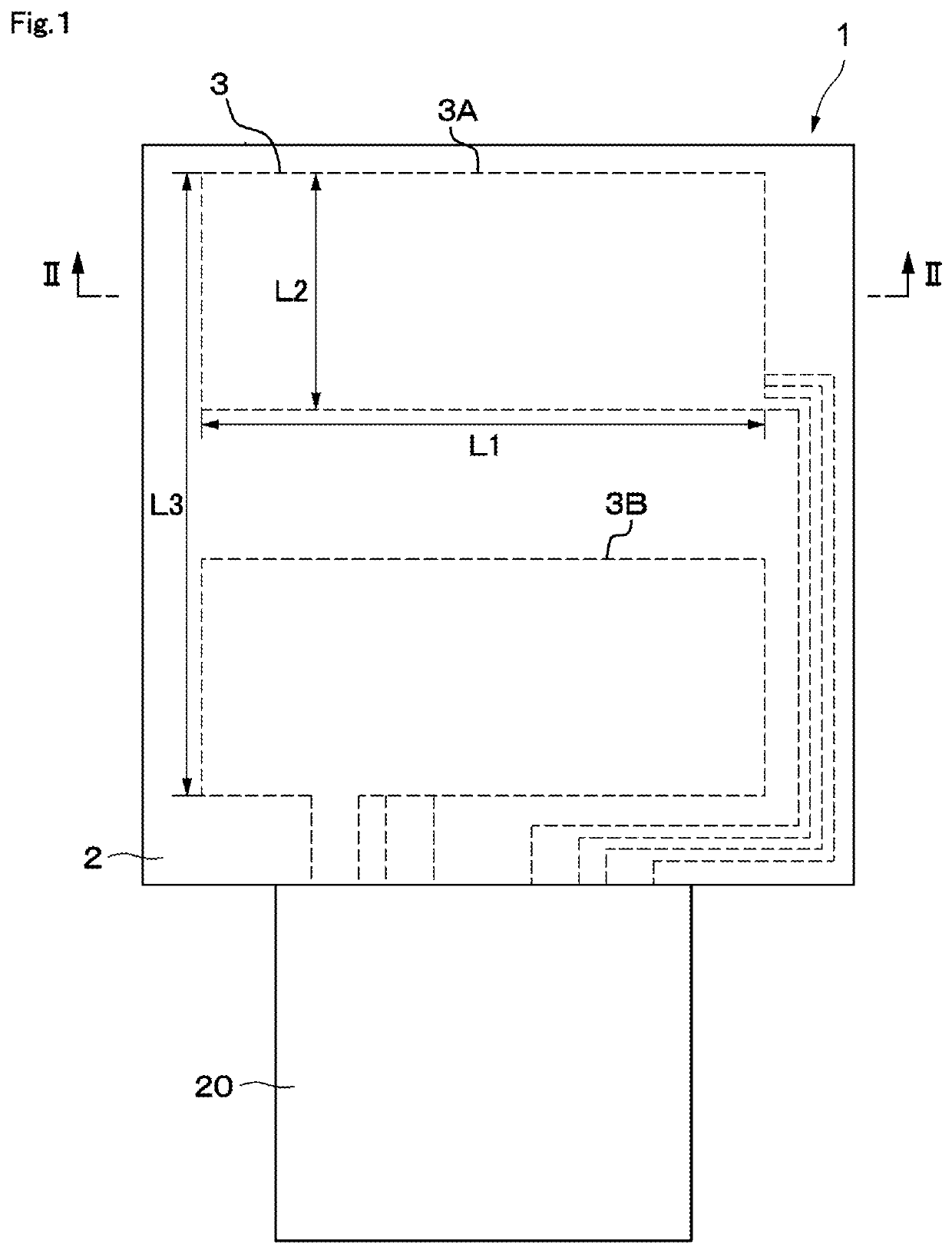
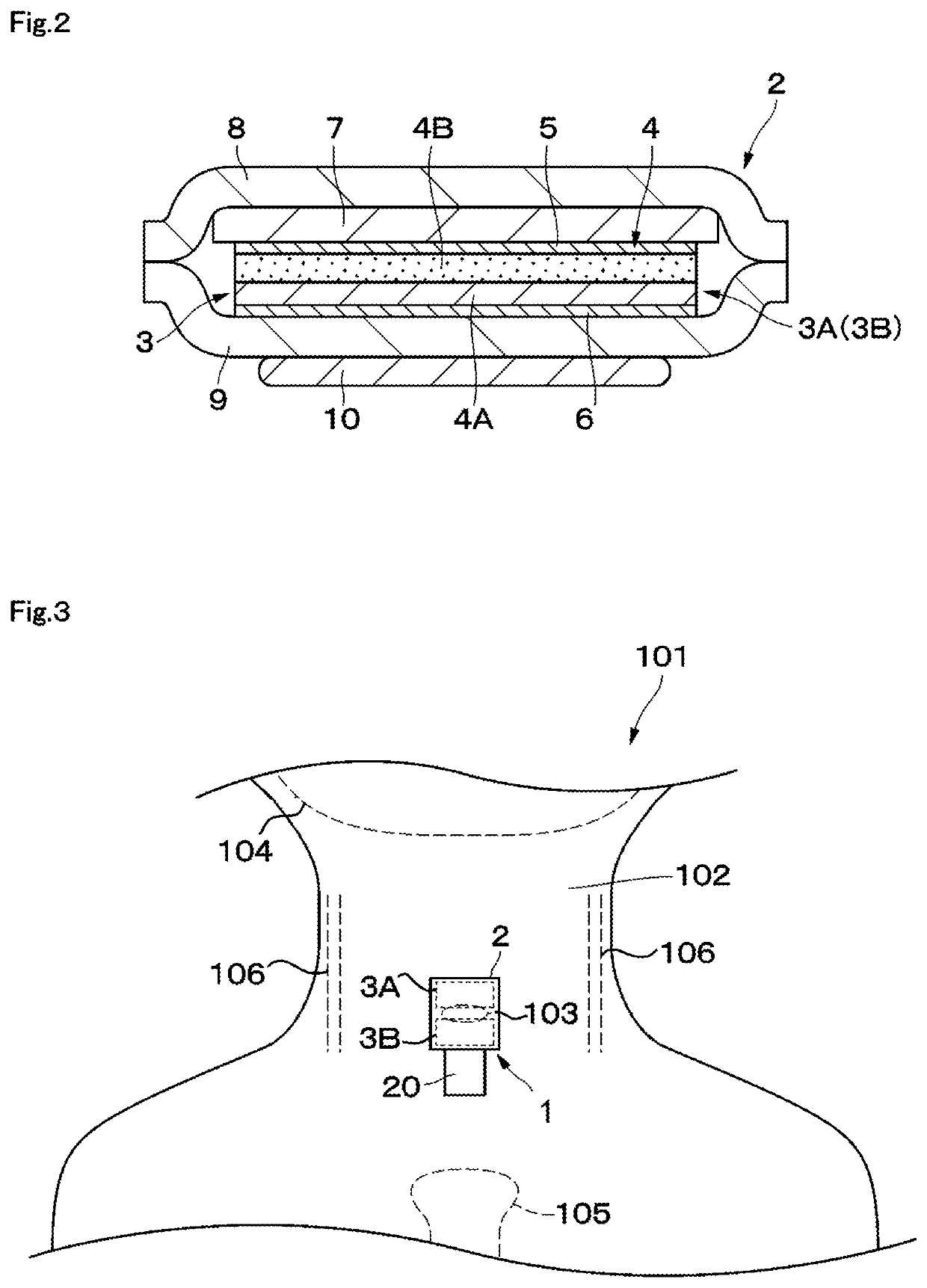
[0041]FIG. 1 to FIG. 5 illustrate a swallowing sensor 1 according to the present disclosure. The swallowing sensor 1 includes a sensor portion 2 configured to detect swallowing of the subject 101 (human body), and a body 20 configured to process signals outputted from the sensor portion 2.

[0042]For example, the sensor portion 2 as a whole has a rectangular shape and is located on one end side of the swallowing sensor 1 in a vertical direction (upper side in FIG. 1). As illustrated in FIG. 2, the sensor portion 2 includes a piezoelectric film sensor 3, an insulating film 7, and shield films 8 and 9. As illustrated in FIG. 3, the sensor portion 2 is located within a range of movement of thyroid cartilage 103, which occurs along with swallowing, and is attached to the skin of the anterior neck region 102 of the subject 101.

[0043]The jawbone 104 is located above the thyroid cartilage 103 and the breastbone 105 is located below the thyroid cartilage 103. A pair of the carotid arteries 10...

second embodiment

[0124]The second embodiment provides the structure in which one sensing portion 33A and one sensing portion 33B whose polarities are reversed are arrayed vertically. The piezoelectric film sensor 33 outputs the addition signal Sa obtained by adding together the signals obtained along with the deformation of the plurality of sensing portions 33A and 33B. Therefore, the swallowing determination can be facilitated without increasing the data amount.

[0125]This point is described in detail with reference to FIG. 19. The broken line in FIG. 19 represents an output signal in a comparative example in which the two sensing portions 33A and 33B are connected in parallel with the same polarities (unreversed polarities). The comparative example corresponds to a case of a single sensing portion. As illustrated in FIG. 19, in the case of the comparative example, an upward peak P31 occurs around 1.5 seconds and then two relatively gentle downward peaks P32 and P33 occur. However, the pattern does ...


PUM


Abstract

A piezoelectric film sensor (3) of a swallowing sensor (1) includes a plurality of sensing portions (3A) and (3B) in a longitudinal direction of the neck region. The piezoelectric film sensor (3) is located within a range of movement of thyroid cartilage (103), which occurs along with swallowing, and is attached to skin of an anterior neck region (102). The piezoelectric film sensor (3) individually outputs analog signals (S1a) and (S2a) along with deformation of the plurality of sensing portions (3A) and (3B). The swallowing sensor (1) includes pre-processing units (21) and (22) and a signal processing unit (23). Each of the pre-processing units (21) and (22) separates the analog signal (S1a) or (S2a) into a displacement signal that is a low frequency component and a sound signal that is a high frequency component. The signal processing unit (23) determines whether the swallowing occurs based on the displacement signal.

Description

[0001]This is a continuation-in-part of International Application No. PCT / JP2018 / 011055 filed on Mar. 20, 2018 which claims priority from Japanese Patent Application No. 2017-065309 filed on Mar. 29, 2017. The contents of these applications are incorporated herein by reference in their entireties.BACKGROUND OF THE DISCLOSUREField of the Disclosure[0002]The present disclosure relates to a swallowing sensor configured to detect a swallowing action.Description of the Related Art[0003]Pneumonia is one of the leading causes of death in Japan. The majority of people who die of pneumonia are elderly people over 65 years old. Aspiration pneumonia is the most frequent pneumonia among elderly people. There are increasing dysphagic patients along with aging society.[0004]Aspiration may be caused by an abnormality of timing in addition to a slowdown in swallowing reflex and muscle weakness. That is, aspiration is likely to occur when swallowing occurs in an inspiratory phase or when an apneic p...

Claims


Application Information

Patent Timeline
IPC IPC(8): A61B5/00A61B5/11
CPCA61B5/0002A61B5/4205A61B2562/0247A61B5/6822A61B5/11A61B2562/0261A61B5/6832
Inventor SHIMUTA, TORUOBATA, TAKAYOSHI
Owner MURATA MFG CO LTD
Learn More