Engine control device

Active Publication Date: 2020-01-23
MAZDA MOTOR CORP
View PDF10 Cites 7 Cited by
  • Summary
  • Abstract
  • Description
  • Claims
  • Application Information

AI Technical Summary

Benefits of technology

[0018]According to the present invention, it is possible to provide an engine

Problems solved by technology

However, if the engine is used in an operating aspect in which the frequency of high-load operation is low for example, the exhaust gas does not reach a high temperature, and therefore there are cases where a temperature sufficient for soot oxidation in the regeneration control is not obtained.
In

Method used


Image

  • Engine control device
  • Engine control device
  • Engine control device

Examples


Embodiment Construction

Overall Configuration of Engine

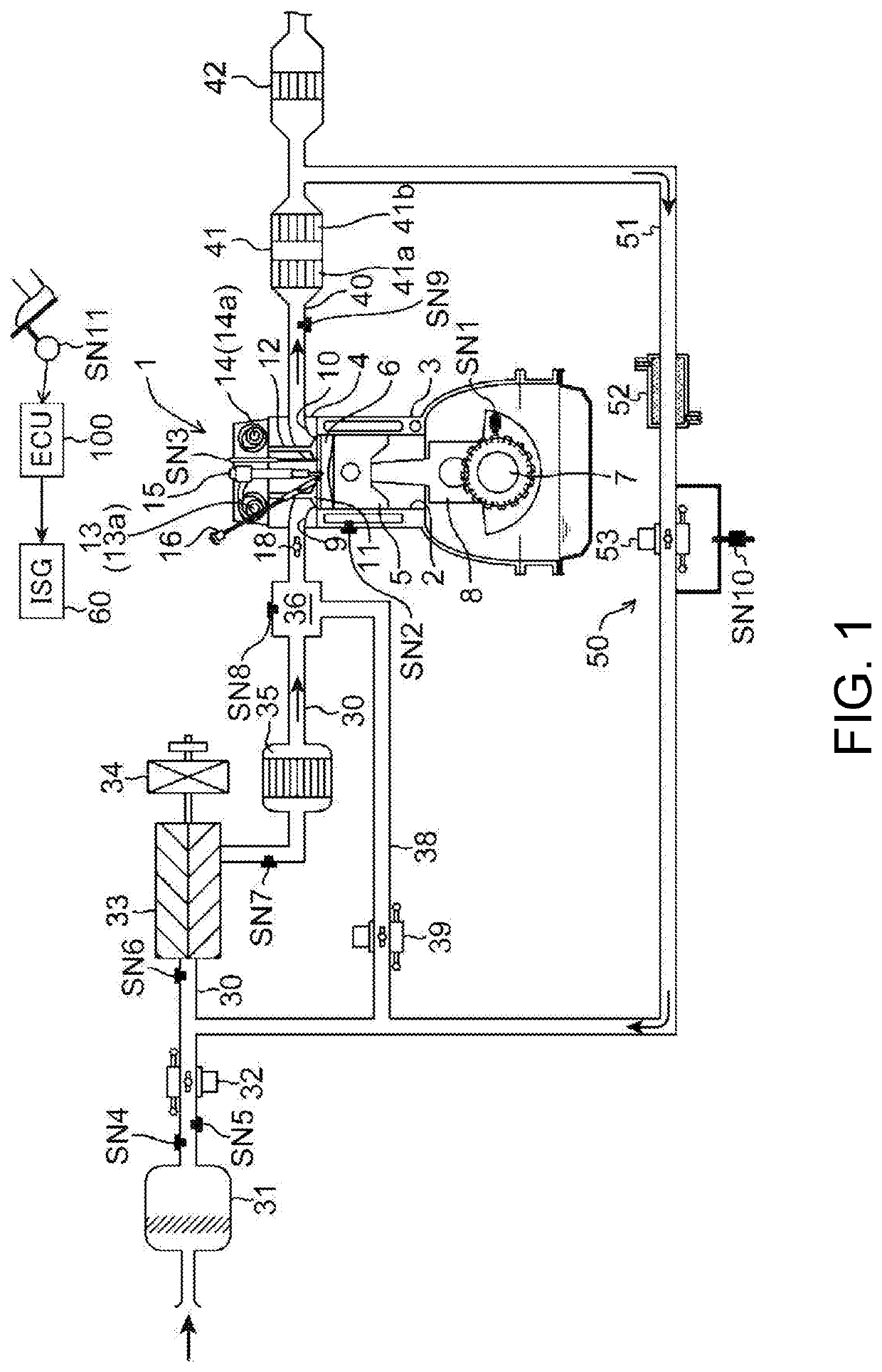
[0026]FIG. 1 is a system diagram showing an embodiment of an engine to which a control device of the present invention is applied. The engine shown in FIG. 1 is a four-cycle gasoline direct-injection engine that is installed in a vehicle as a power source for travelling, and includes an engine body 1, an intake path 30 for the flow of intake air that is to be introduced to the engine body 1, an exhaust passage 40 for the flow of exhaust gas that is to be discharged from the engine body 1, and an external exhaust gas recirculation (EGR) device 50 by which part of the exhaust gas flowing through the exhaust passage 40 is returned to the intake path 30.

[0027]The engine body 1 includes a cylinder block 3 in which a cylinder 2 has been formed, a cylinder head 4 that is attached to the upper face of the cylinder block 3 so as to close off the cylinder 2 from above, and a piston 5 that is inserted into the cylinder 2 and can reciprocate therein. The engine bo...


PUM


Abstract

An engine control device that can suppress thermal degradation of a particulate filter is provided. The device executes a fuel injection control module that restricts the supply of fuel by an injector if a fuel cutting condition is satisfied, an accumulation estimation module that estimates the accumulated amount of soot trapped in a GPF, and a regeneration control module that performs regeneration control for regenerating the GPF by burning soot if the accumulated soot amount exceeds a predetermined setting amount. A fuel cut prohibition line is set in advance and defines a prohibition temperature at which fuel cutting control is to be prohibited in accordance with the accumulated soot amount. The device further executes a prohibition control module that prohibits performance of fuel cutting control by the fuel injection control module if the temperature of the GPF is higher than the prohibition temperature.

Description

CROSS-REFERENCES TO RELATED APPLICATIONS[0001]This application claims priority to Japanese Patent Application No. 2018-134208 filed on Jul. 17, 2018, the entire contents of which are incorporated herein by reference.TECHNICAL FIELD[0002]The present invention relates to an engine control device for an engine in which a particulate filter is arranged in an exhaust passage.BACKGROUND ART[0003]An exhaust passage for exhaust gas that is to be discharged from an engine body is sometimes provided with a particulate filter for trapping particulates (soot) that are contained in the exhaust gas. As the accumulated amount of soot in the particulate filter rises, the filtering performance falls. For this reason, when the accumulated amount of soot exceeds a certain amount, regeneration control is performed to proactively supply oxygen to the particulate filter and oxidize (burn) the accumulated soot.[0004]However, if the engine is used in an operating aspect in which the frequency of high-load ...

Claims


Application Information

Patent Timeline
IPC IPC(8): F02D41/02F01N3/029B60W30/18
CPCF02D41/029F02D2200/101F01N3/029B60W30/18127F01N3/0253F01N9/002F01N2260/04F01N2430/06F01N2560/06F01N2900/12F01N2900/1404F01N2900/1606F02D41/123F02D2200/0802F02D2200/0812Y02T10/40
Inventor KURITA, HIROYUKITANAKA, EIJIROITO, TAKEATSUYOSHIDA, HIROSHI
Owner MAZDA MOTOR CORP
Why Eureka
Try Eureka