Automotive dynamoelectric machine

a dynamoelectric machine and motor technology, applied in the direction of dynamo-electric components, magnetic circuit rotating parts, magnetic circuit shapes/forms/construction, etc., can solve the problems of heat degradation of the brush apparatus connector, etc., to achieve the effect of improving noise tolerance and suppressing heat degradation

Active Publication Date: 2006-10-17
MITSUBISHI ELECTRIC CORP
View PDF11 Cites 2 Cited by
  • Summary
  • Abstract
  • Description
  • Claims
  • Application Information

AI Technical Summary

Benefits of technology

[0010]According to the present invention, the brush holder is accommodated together with the sensor unit inside the accommodating portion formed on the end surface at the first end of the housing. Thus, the brush holder, the sensor unit, the brush connector unit, and the sensor connector unit are separated from a stator constituting a heat source, suppressing heat degradation of the brush holder, the sensor unit, the brush connector unit, and the sensor connector unit. In addition, the sensor unit and the sensor connector unit are separated from a magnetic circuit portion, improving noise tolerance.

Problems solved by technology

In conventional automotive dynamoelectric machines, the brush apparatus, which is a resin-molded part, is disposed in the vicinity of a stator, which is a heat source, and heat degradation of the brush apparatus has been a problem.
Thus, this brush apparatus connector is disposed in the vicinity of the stator, which is a heat source, and heat degradation of the brush apparatus connector has also been a problem.

Method used


Image

  • Automotive dynamoelectric machine
  • Automotive dynamoelectric machine
  • Automotive dynamoelectric machine

Examples


embodiment 1

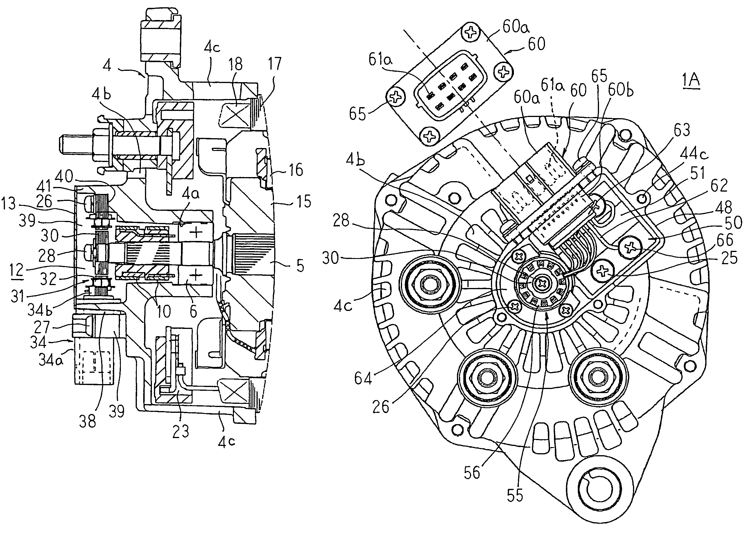
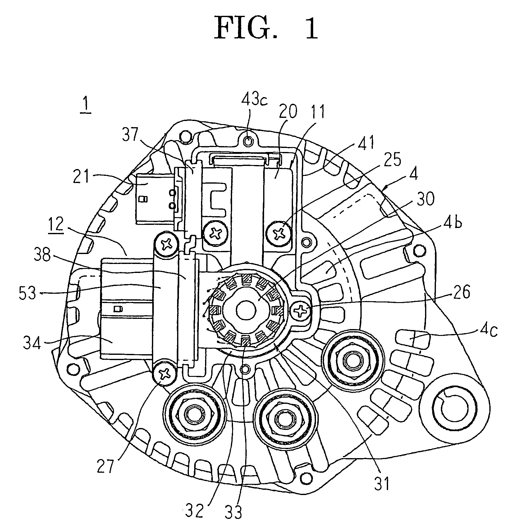
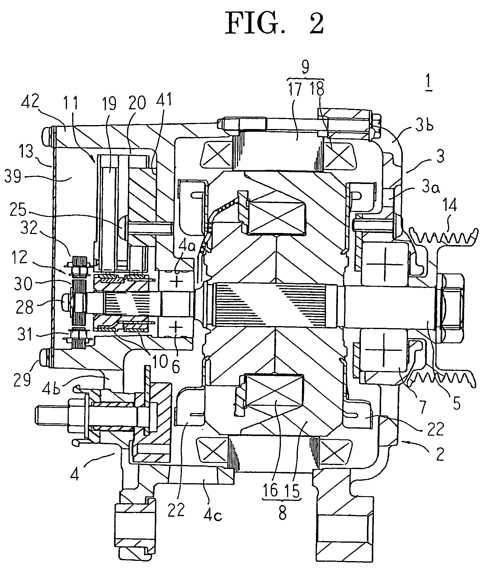
[0025]FIG. 1 is a rear-end end elevation showing an automotive dynamoelectric machine according to Embodiment 1 of the present invention, FIG. 2 is a longitudinal section showing the automotive dynamoelectric machine according to Embodiment 1 of the present invention, and FIG. 3 is a cross section showing a vicinity of a rotor position detecting apparatus of the automotive dynamoelectric machine according to Embodiment 1 of the present invention. FIG. 4 is a rear-end end elevation showing a rear bracket in the automotive dynamoelectric machine according to Embodiment 1 of the present invention, and FIGS. 5A and 5B are diagrams explaining a configuration of the rotor position detecting apparatus in the automotive dynamoelectric machine according to Embodiment 1 of the present invention, FIG. 5A being a front elevation thereof and FIG. 5B being a side elevation thereof. FIGS. 6A to 6C are diagrams explaining a construction of a sensor coil of the rotor position detecting apparatus in ...

embodiment 2

[0070]FIG. 7 is a rear-end end elevation showing an automotive dynamoelectric machine according to Embodiment 2 of the present invention, FIG. 8 is a longitudinal section showing the automotive dynamoelectric machine according to Embodiment 2 of the present invention, FIG. 9 is a rear-end end elevation showing a rear bracket in the automotive dynamoelectric machine according to Embodiment 2 of the present invention, FIG. 10 is a rear-end end elevation showing a mounted state of a brush holder in the automotive dynamoelectric machine according to Embodiment 2 of the present invention, and FIG. 11 is a diagram explaining a construction of a connector unit in the automotive dynamoelectric machine according to Embodiment 2 of the present invention. Moreover, FIG. 7 shows a state in which an end plate has been removed. Portions the same as or corresponding to those in the automotive dynamoelectric machine 1 according to Embodiment 1 above will be given the same numbering below, and expla...


PUM


Abstract

An accommodating space is formed on an end surface at a first axial end of a rear bracket so as to envelop an end portion region of a shaft, and a brush holder and a sensor unit are disposed in the accommodating space. A brush connector unit and a sensor connector unit are disposed so as to project out of the accommodating space, and electrical connection between brushes and the brush connector unit and signal connection between the sensor unit and the sensor connector unit are performed inside the accommodating space.

Description

BACKGROUND OF THE INVENTION[0001]1. Field of the Invention[0002]The present invention relates to an automotive dynamoelectric machine having a rotor position detecting apparatus for detecting a rotation angle of a rotor.[0003]2. Description of the Related Art[0004]In conventional automotive dynamoelectric machines, a rotor position detecting apparatus is mounted to a tip portion of a shaft so as to be accommodated in and fixed to an accommodating portion formed on an outer peripheral surface of a rear bracket, and detects a rotation angle of a rotor. A brush apparatus is fixed to an inner wall surface of the rear bracket so as to face slip rings fixed to an outer peripheral surface of the shaft, and supplies a field current to a rotor coil in the rotor through the slip rings. (See Patent Literature 1, for example.)[0005]Patent Literature 1: Japanese Patent Laid-Open No. 2003-061312 (Gazette)[0006]In conventional automotive dynamoelectric machines, the brush apparatus, which is a res...

Claims


Application Information

Patent Timeline
Patent Type & Authority Patents(United States)
IPC IPC(8): H02K11/00H02K5/22H02K5/20H02K5/14H02K19/36
CPCH02K5/141H02K5/225H02K19/36H02K11/00
Inventor UTSUMI, YOSHINOBUMORIKAKU, HIDEKIASAO, YOSHIHITO
Owner MITSUBISHI ELECTRIC CORP
Why Eureka
Try Eureka