Flexing slot for plug valve insert

a plug valve and insert technology, applied in the direction of plug valves, valve arrangements, mechanical equipment, etc., can solve the problems of limited service life of plug valves, unusable main body, accelerate corrosion, etc., and achieve the effect of optimum sealing characteristics and same sealing performan

Active Publication Date: 2020-01-23
BLUECORE COMPLETIONS LLC
View PDF9 Cites 5 Cited by
  • Summary
  • Abstract
  • Description
  • Claims
  • Application Information

AI Technical Summary

Benefits of technology

[0012]One embodiment of the present inventive principles is a high pressure plug valve consisting of a cylindrical plug with a single tapered insert, which has slots enabling a preferential deflection in the same axis as the fluid bore to ensure optimum sealing characteristics. In some embodiments, the tapered insert is machined out of a single piece of high grade steel and is used without being cut in half. Preferably, equal slots are machined into the insert on opposing sides, thereby allowing the transverse opposing sides of the insert, which create the sealing interfaces between plug and valve body, to flex (i.e. move in a transverse direction parallel to the bore). Advantageously, the flexible single insert retains the exact concentricity required on internal and external faces, which gives the same sealing performance as split inserts without the twisting that is detrimental to the sealing performance.

Problems solved by technology

Plug valves have a service life that is limited by the condition of the main body.
Internal parts can be replaced but eventually the deterioration of the sealing insert to main body interface, due to corrosion, wear, erosion and eventual washout, which leads to an unusable main body.
The root cause of this deterioration is the inherent design of these types of valves, which including small gaps between the internal sealing parts that allow movement of the main sealing interface (i.e., the rotation of a plug between the inserts in a plug valve).
Without these gaps plug will lock-up due to friction.
Moreover, the fracing is typically preceded and followed by an acid wash of 15% hydrochloric acid, which accelerates corrosion.
With the high velocity of abrasive fracing fluid, any weakness or point of turbulence can very quickly lead to a washout of a seal area or any interface.
If an area or interface adjoins the valve main body, then the life of the main valve body is severely limited.
Even with this procedure, the moving sealing faces have a very limited service life and are replaced frequently.
On larger plug valves the industry has moved towards split tapered inserts which provide better sealing at high pressures but also create other issues.
These lower grade steels like the ductile iron are softer and wash-out easily leading to consequential washout and failure of more expensive parts like the plug and sometimes the body of the valve.
This solution however creates a high friction interface with the plug and also does not solve the problem of ensuring optimum sealing.

Method used


Image

  • Flexing slot for plug valve insert
  • Flexing slot for plug valve insert
  • Flexing slot for plug valve insert

Examples


Embodiment Construction

[0024]The problems being solved and the solutions provided by the embodiments of the principles of the present inventions are best understood by referring to FIGS. 1 to 7 of the drawings, in which like numbers designate like parts.

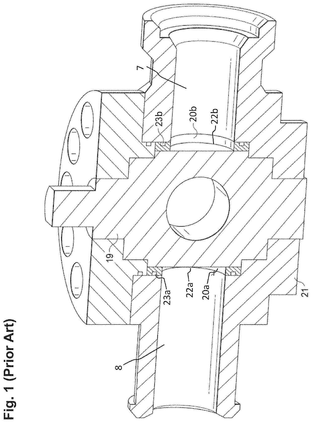
[0025]FIG. 1 is a schematic cross-sectional side view of a prior art cylindrical design plug valve having a cylindrical plug 19 sealing in a rotating fashion against two stationary split inserts 20a and 20b. These inserts 20 are sealed against the body 21 and have a tolerance gaps at 22a, 22b to allow the plug 19 to move rotationally with respect to the inserts 20. The inserts 20 are sealed against the body21 with seals 23a, 23b and they are stationary relative to the body. As the seal between the inserts 20 and the body 21 is affected by elastomeric seals 23, the gap and perfect alignment of the inserts 20 with respect to the body 21 is not critical, though of course it must be sufficiently small to avoid extrusion of the seals under pressure. The seal be...


PUM


Abstract

An insert adapted for use in a plug valve includes a single-piece body having an inner sidewall adapted to interface with a sidewall of a valve plug. First and second opposing apertures are each defined through the single-piece body for selective alignment with a flow bore of the valve plug. First and second opposing slots are each defined through the single-piece body at an angle to the first and second opposing apertures for allowing the body to flex in the direction of the first and second opposing apertures.

Description

CROSS-REFERENCE TO RELATED APPLICATION[0001]The present application claims the benefit of U.S. Provisional Patent Application Ser. No. 62 / 699,641, filed Jul. 17, 2018, which is incorporated herein by reference in its entirety for all purposes.FIELD OF INVENTION[0002]This invention relates in general to fluid drilling equipment and in particular to high pressure valves subjected to severe operating conditions, such as the high pressures, high flow rates, and abrasive fluids commonly found in hydraulic fracturing operations and other oil and gas drilling applications.BACKGROUND OF INVENTION[0003]Plug valves have a service life that is limited by the condition of the main body. Internal parts can be replaced but eventually the deterioration of the sealing insert to main body interface, due to corrosion, wear, erosion and eventual washout, which leads to an unusable main body. The damaged main body typically needs to be repaired in an intrusive manner such as welding. The root cause of ...

Claims


Application Information

Patent Timeline
Patent Type & Authority Applications(United States)
IPC IPC(8): F16K5/04
CPCF16K5/0407F16K5/0471F16K5/0464F16K5/0478F16K5/168F16K5/184
Inventor CUIPER, GLEN H.HARREL, TRAVISLEUCHTENBERG, CHRISTIAN
Owner BLUECORE COMPLETIONS LLC
Why Eureka
Try Eureka