
Monolithic Structured Light Projector

Pending Publication Date: 2020-01-23
II VI DELAWARE INC
View PDF4 Cites 2 Cited by
  • Summary
  • Abstract
  • Description
  • Claims
  • Application Information

AI Technical Summary

Benefits of technology

The present invention (a structured light projector) solves the need for a separate collimator component and offers a more compact and reliable alternative. Direct fabrication onto a laser diode light source makes this a monolithic, integrated configuration. A specialized DOE (dispersive optical element) is used to eliminate collimator-DOE alignment, allowing for the use of a discrete light source. Even with a discrete specialized DOE, this invention offers improved compactness and reliability.

Problems solved by technology

The alignment tolerances necessarily add to the expense of the projector, as well as to the time and effort required to manufacture the assembly.
The tight alignment tolerances also impact the packaging requirements.

Method used


Image

  • Monolithic Structured Light Projector
  • Monolithic Structured Light Projector
  • Monolithic Structured Light Projector

Examples


Embodiment Construction

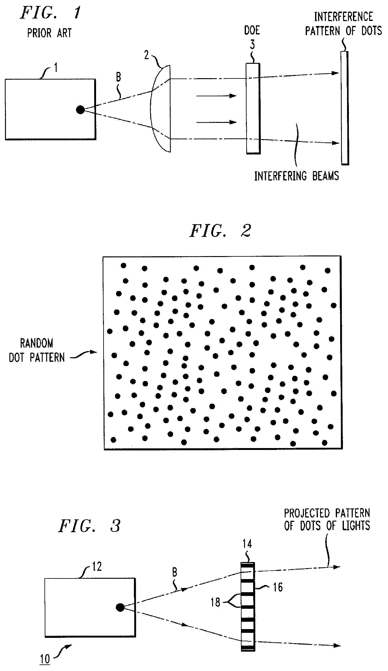
[0020]FIG. 3 is a simplified block diagram of an exemplary structured light projector 10 formed in accordance with the principles of the present invention. Similar to the prior art configuration described above, a light source 12 is used to emit a beam that diverges as it exits source 12 and continues to diverge as a non-collimated beam as it propagates along an output path. In accordance with the present invention, a specialized DOE 14 is configured to interact with the non-collimated beam and create a pattern of light dots that may be essentially the same as that shown in FIG. 2.

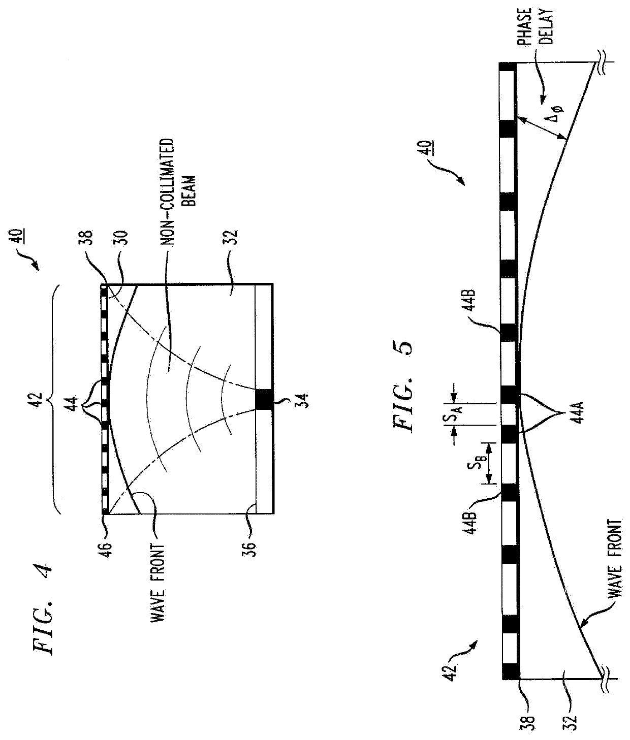
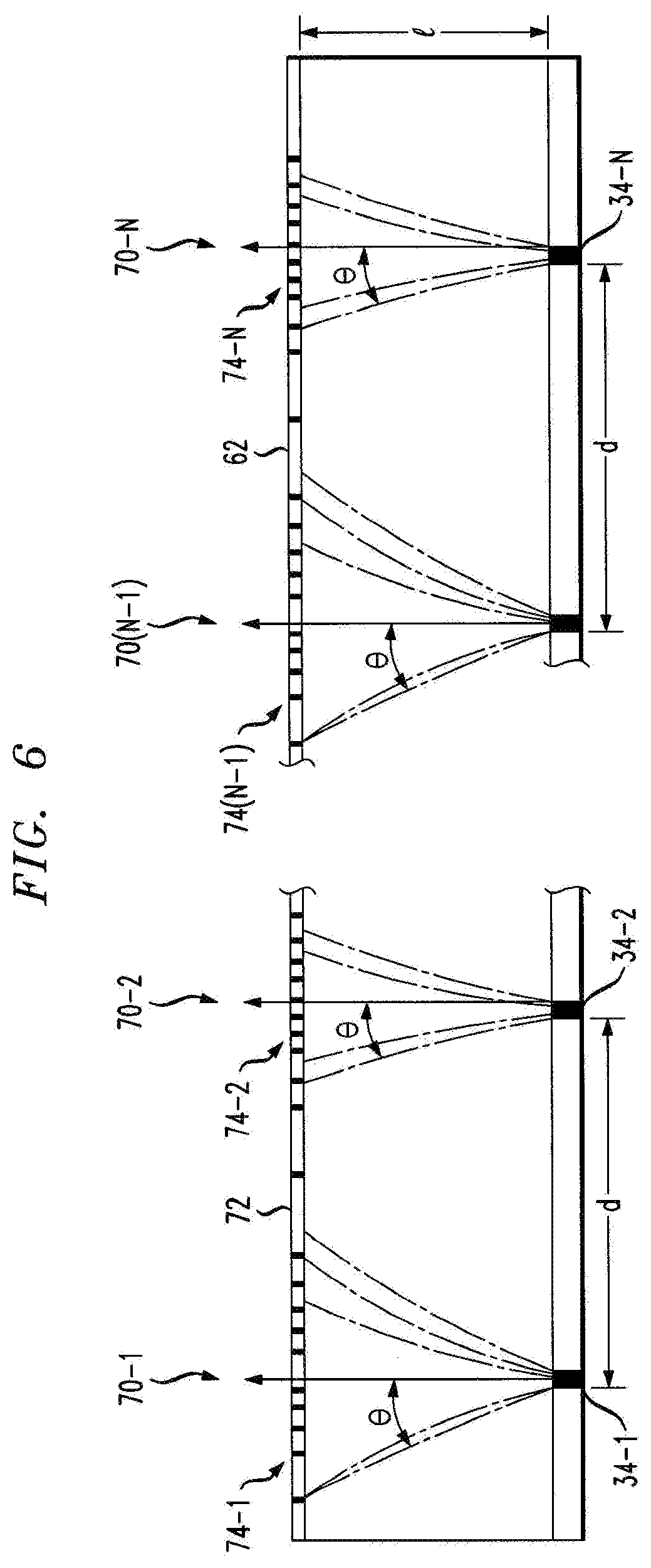
[0021]As will be discussed in detail below, specialized DOE 14 is formed to exhibit a non-uniform pattern 16 of grating features 18, as opposed to typical DOEs that exhibit a uniform configuration to create the desired interference pattern. In particular, pattern 16 may be non-uniform in terms of the spacing between adjacent features 18 across the surface of element 14, or non-uniform in terms of thickness...


PUM


Abstract

A structured light projector for generating a far-field image of light dots in a defined pattern is proposed, where the structured light projector includes a light source providing as an output a non-collimated light beam and a specialized diffractive optical element disposed to intercept the non-collimated light beam. The specialized diffractive optical element is formed to exhibit a non-uniform pattern of grating features configured to compensate for the non-planar wavefront and phase retardation of the non-collimated output beam, providing as an output of the projector an interference pattern of light dots exhibiting the desired configuration.

Description

TECHNICAL FIELD[0001]The present invention relates to a structured light projector and, more particularly, to a monolithic structured light projector that eliminates the need for a separate collimator to provide beam shaping.BACKGROUND OF THE INVENTION[0002]Structured light projectors are being developed for applications where specific patterns of light “dots” are used to cast a pattern of coded light or information. Applications such as 3D sensing, mapping, and the like depend on the use of this type of optical source. FIG. 1 is a simplified diagram of a typical prior art structured light projector, including a laser diode 1 that emits a beam B. As shown, the beam is divergent as it exits laser diode 1. The diverging beam is then directed into a collimating lens 2 that functions to focus (shape) the diverging beam into a set of parallel rays (i.e., a collimated beam) that presents a planar wavefront. The collimated beam is then directed into a diffractive optical element (DOE) 3 th...

Claims


Application Information

Patent Timeline
IPC IPC(8): G02B5/18H01S5/022H01S5/183H01S5/42H01S5/00
CPCH01S5/183G02B5/1828H01S5/005H01S5/423G02B5/1857H01S5/0224G02B5/1842G02B27/0944G02B27/20H01S2301/20H01S5/02257G02B27/44G03B21/14H01S5/0234
Inventor TEISSIER, JEAN AXEL EDMONDBOUCART, JULIEN
Owner II VI DELAWARE INC
Learn More