Polarizing reflector for multiple beam antennas

a technology of reflectors and antennas, applied in the direction of antenna earthings, antennas, electrical devices, etc., can solve the problems of reducing affecting the polarization efficiency of the antenna, and affecting the polarization efficiency of the circular polarization

Active Publication Date: 2020-01-23
THALES SA
View PDF0 Cites 12 Cited by
  • Summary
  • Abstract
  • Description
  • Claims
  • Application Information

AI Technical Summary

Benefits of technology

[0039]the geometry of the patch array, the thickness and the dielectric permittivity of the substrate, and the geometry of the elongated metallic strips are tuned so that a first resonance frequency of the dipole mode and a first resonance frequency of the aperture mode, higher than first resonance frequency of the dipolar mode, surround the single frequency wideband of the single operating wideband or the first frequency band of the dual operating band;
[0040]the geometry of the patch array, the thickness and the di

Problems solved by technology

The generation of this circular polarization is known as a sensitive issue and is usually performed at feed level for a reflector antenna.
These polarizers add mass and contribute to the bulkiness of the feed array, especially in low frequency bands, such as at L, S, C bands.
This approach often requires a multi-layer design of the screens, resulting in relatively high insertion losses performance and increased manufacturing complexity.
Such multi-layer screens are also characterized by relatively poor axial ratio performances over the scanning range and over the frequency bandwidth.
A first technical problem is to increase the stability and/or decrease the sensitiv

Method used


Image

  • Polarizing reflector for multiple beam antennas
  • Polarizing reflector for multiple beam antennas
  • Polarizing reflector for multiple beam antennas

Examples


first embodiment

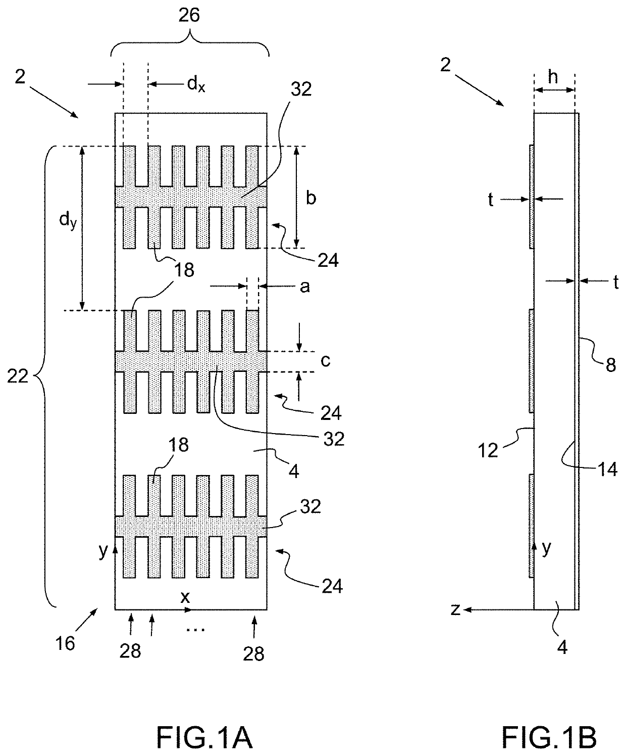
[0090]According to the FIGS. 1A-1B and the invention, a polarizing reflector 2 suited to broadband satellite applications is configured for converting a same linear polarization into a given circular polarization handedness over one frequency band, or into a given circular polarization handedness over a first frequency band and into the orthogonal handedness over a second frequency band.

[0091]The polarizing reflector 2 comprises a flat dielectric substrate 4, a patch array layer 6 and a ground layer 8.

[0092]The flat dielectric substrate 4 is delimited between a first surface 12 and a second surface 14, having a thickness h and a dielectric permittivity εr.

[0093]The patch array layer 6 is formed by a bi-dimensionally periodic lattice 16 of thin metallic patches 18 laid on the first surface 12 of the substrate 4, the periodic lattice 16 having a first set 22 of patch rows 24 oriented along a first direction x with a periodicity dx and a second set 26 of patch columns 28 oriented along...

second embodiment

[0156]According to FIG. 13 and the invention, a polarizing reflector 213 suited to broadband satellite applications is configured for converting a same linear polarization into a given circular polarization handedness over one frequency band, or into a given circular polarization handedness over a first frequency band and into the orthogonal handedness over a second frequency band.

[0157]The polarizing reflector 213 comprises a flat dielectric substrate 214, a patch array layer 216 and a ground layer 218.

[0158]The flat dielectric substrate 214 is delimited between a first surface 222 and a second surface 224, having a thickness h and a dielectric permittivity εr.

[0159]The patch array layer 216 is formed by a first bi-dimensionally periodic lattice 226 of thin metallic patches 228 and a second bi-dimensionally periodic lattice 230 of thin metallic patches 228, both laid on the first surface 222 of the substrate 214.

[0160]The first and second periodic lattices 226, 230 having each a fi...

third embodiment

[0182]According to the FIG. 16 and the polarizing reflector, a flat polarizing reflector 352 for a broadband antenna is locally illuminated at normal or oblique incidence by an electromagnetic source 354 (or feeder) having a predetermined radiation pattern to the flat polarizing reflector.

[0183]The flat polarizing reflector 352 is configured for converting locally a linear polarization Einc into a given local circular polarization handedness over one frequency band when operating in a single wideband at a local normal or oblique incidence illuminated by a local plane wave originated from a predetermined radiation source pattern, or into a first local circular polarization handedness over a first frequency band and into a second local polarization handedness over a second frequency, the first and the second local circular polarization handedness being substantially equal or orthogonal when operating in dual-band at normal or oblique incidence illuminated by a local plane wave origina...


PUM


Abstract

A polarizing reflector for broadband antennas includes a flat dielectric substrate, a patch array layer formed by a bi-dimensionally periodic lattice of thin metallic patches along first and second perpendicular directions x, y, and a ground layer. All the patches have a same shape elongated along the second direction y and form electric dipoles when electrically excited along the second direction y. For each row the patches of the said row are interconnected by an elongated metallic strip oriented along the first direction x and having a width c. The geometry of the patch array, the thickness h and the dielectric permittivity εr of the substrate, and the width c of the elongated metallic strips are tuned so that the patch array including the elongated metallic strips induces a fundamental aperture mode and a complementary fundamental dipolar mode along two orthogonal TE and TM polarizations within a single operating frequency band or two separate operating frequency bands, and the differential phase between the two fundamental modes over the single or the first and second frequency bands being equal to ±90° or to an odd integer multiple of ±90°. The polarizing reflector can comprise also a curved substrate and a patch array layer formed by a bi-dimensionally lattice of metallic patches along first curvilinear rows and second curvilinear columns.

Description

CROSS-REFERENCE TO RELATED APPLICATIONS[0001]This application claims priority to foreign European patent application No. EP 17306169.8, filed on Sep. 11, 2017, the disclosure of which is incorporated by reference in its entirety.FIELD OF THE INVENTION[0002]The present invention concerns polarizing reflectors or reflecting surfaces for antennas, namely for satellite antennas or ground telecommunication antennas, that reflect an impinging electromagnetic wave while performing the polarization conversion from a linear polarization to a circular polarization.BACKGROUND[0003]The space telecommunication systems, sometimes referred to Satcom systems, often use polarization as a supplemental degree of freedom to increase the spectrum efficiency in multi-beam frequency reuse scheme, and often use circularly polarized electromagnetic (EM) waves to avoid the problems associated with polarization misalignment. This approach is valid for both on-board satellite and terminal antennas. The generat...

Claims


Application Information

Patent Timeline
IPC IPC(8): H01Q15/24H01Q1/48H01Q19/10H01Q21/06
CPCH01Q21/065H01Q1/48H01Q15/24H01Q19/10H01Q15/244
Inventor LEGAY, HERVÉGOUSSETIS, GEORGETANG, WENXINGBRESCIANI, DANIELECHINIARD, RENAUDFONSECA, NELSON
Owner THALES SA
Why Eureka
Try Eureka