Eureka AIR delivers breakthrough ideas for toughest innovation challenges, trusted by R&D personnel around the world.

Composite wood arrangement and method for manufacturing said arrangement

a technology of composite wood and arrangement, which is applied in the direction of structural elements, building components, construction materials, etc., can solve the problems of unsatisfactory durability of the panel and the physical functioning of the building of such a wooden panel that has not been very much examined, and achieves the effect of large carrying capacity and rigid structur

Inactive Publication Date: 2020-02-13
AALTO HAITEK OY
View PDF6 Cites 2 Cited by
  • Summary
  • Abstract
  • Description
  • Claims
  • Application Information

AI Technical Summary

Benefits of technology

The invention provides a simple and cost-effective solution for creating thermally efficient buildings using composite wood arrangements. The method does not require any special tools or skills, and the final structure can be accomplished without chemicals. The flexible joining methods and solutions make the structures excellent for earthquake-prone environments.

Problems solved by technology

The building physical functioning of such a wooden panel has not been very much examined in the Finnish conditions, for example, and the concern has arisen that the durability of the panel is not what is desired due to its manufacturing method.

Method used


Image

  • Composite wood arrangement and method for manufacturing said arrangement
  • Composite wood arrangement and method for manufacturing said arrangement
  • Composite wood arrangement and method for manufacturing said arrangement

Examples


Embodiment Construction

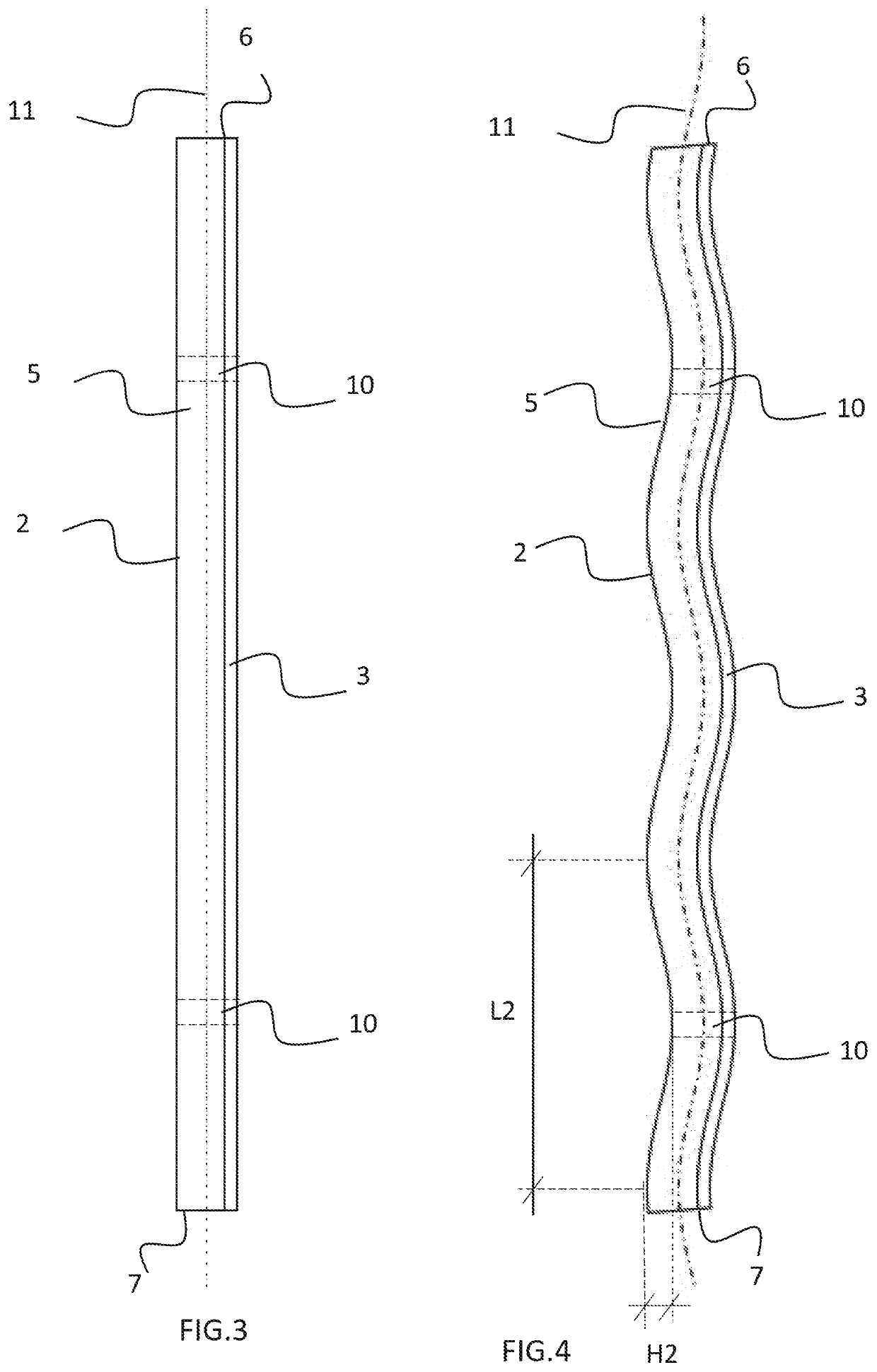
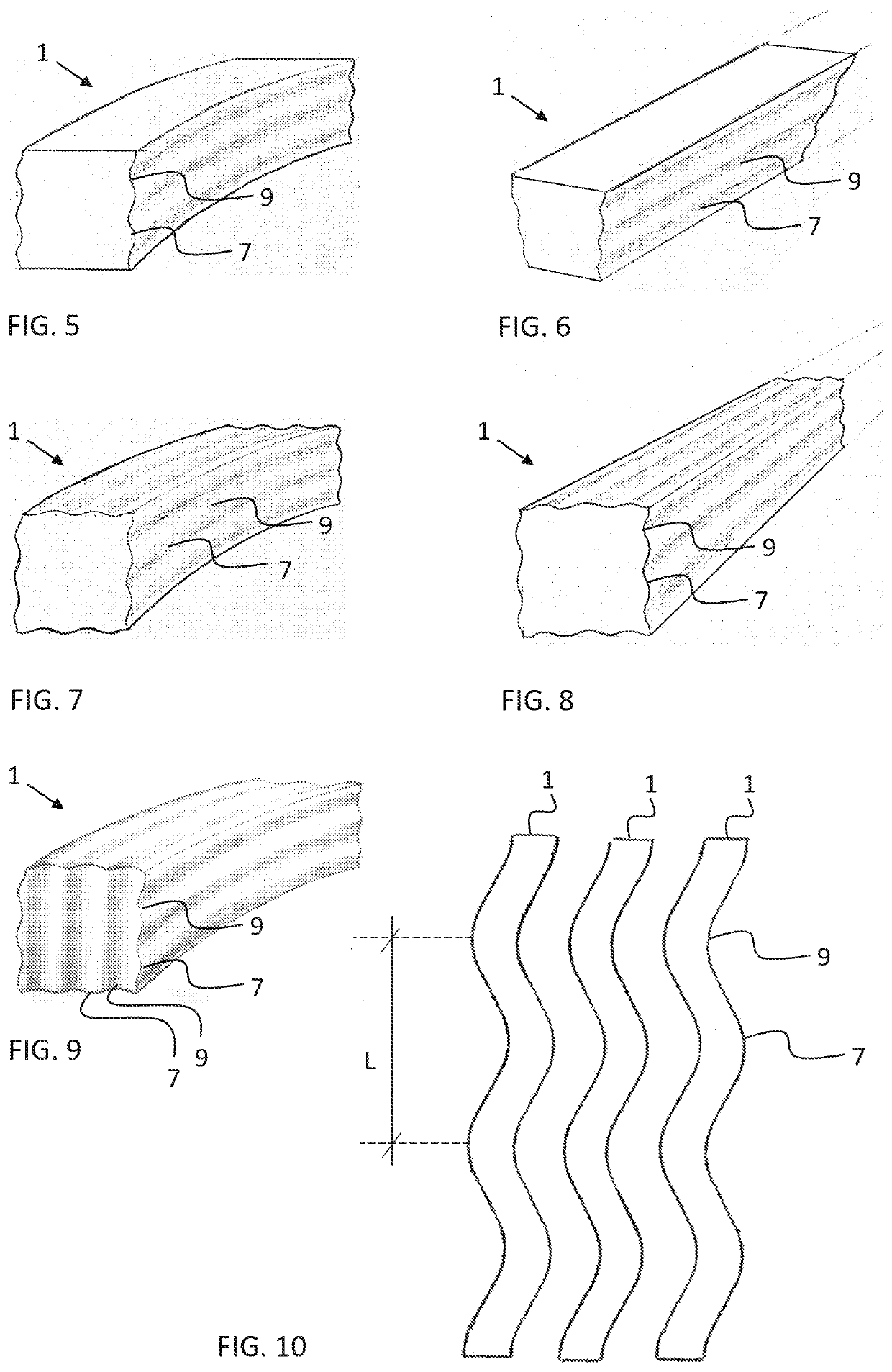
[0041]The present figures do not show the composite wood arrangement in scale but the figures are schematic, illustrating the general structure and operation of the preferred embodiments. The construction components shown by reference numbers in the attached figures then correspond to the construction components marked by reference numbers in this specification.

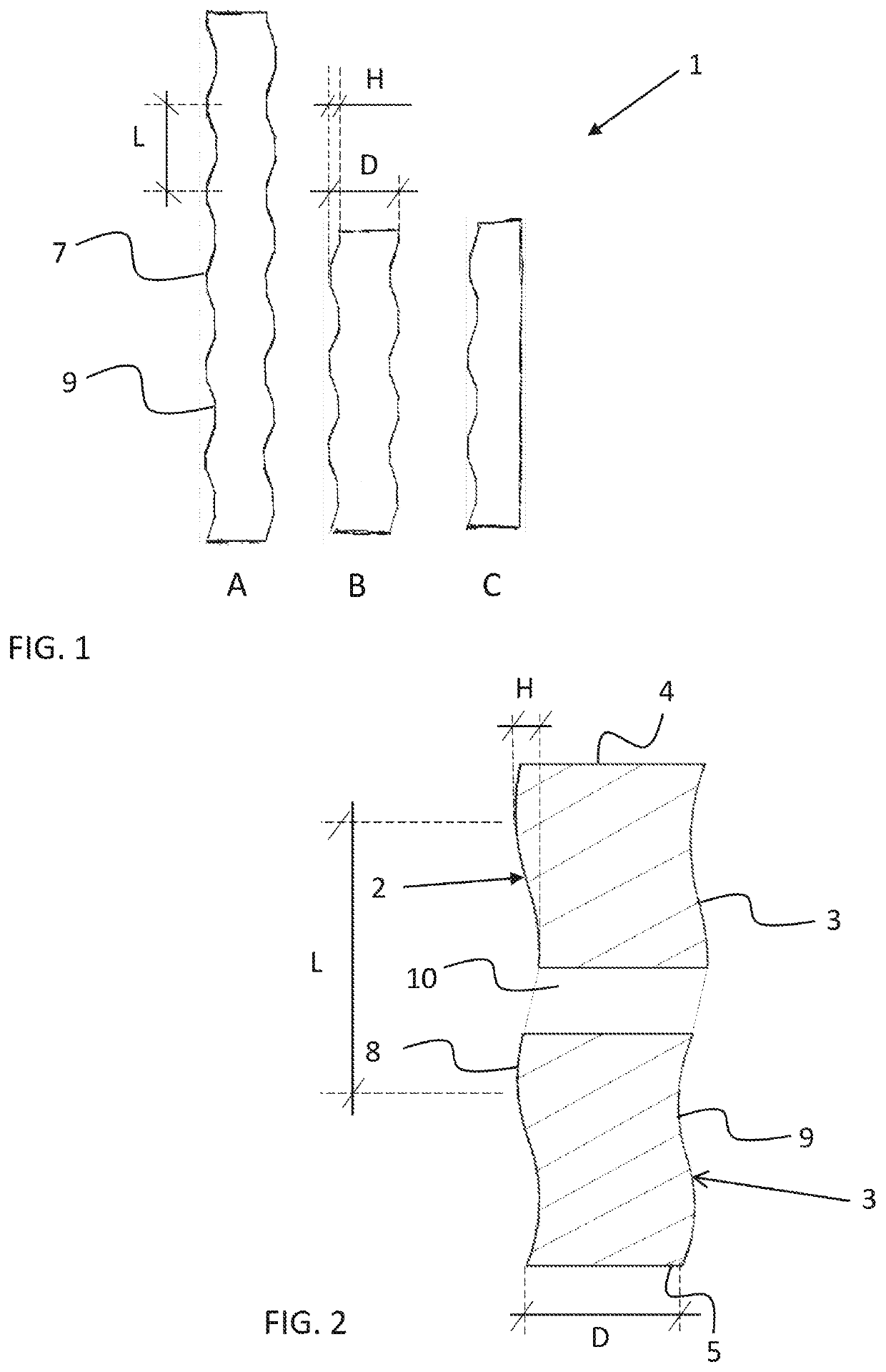
[0042]The present composite wood arrangement is formed by using the exemplary construction components 1 of FIGS. 1 to 3. These advantageously comprise construction components made of wood, whereby FIG. 1 shows advantageous structures A, B and C of the construction component. The construction components then comprise parts made of either raw wood or wood refined by methods known per se, such as heat-treating or pressure treating.

[0043]Although the following will discuss the construction component as a wooden construction part, in particular, it may also be manufactured of plastic, metal, or wood composite, for example. Compare...


PUM

PropertyMeasurementUnit
structureaaaaaaaaaa
thicknessesaaaaaaaaaa
thicknessaaaaaaaaaa

Abstract

The present invention relates to a composite wood arrangement comprising construction components (1) mechanically joined together in a parallel position. Such a construction component comprises at least one profiled side surface (2, 3) and, connecting them together, at least one edge surface (4, 5) and end surfaces (6, 7), perpendicular to the longitudinal axis (11) of the construction component. In the invention, the side surfaces in parallel construction components are adapted in an opposite position in pairs so that profile crests (8) and throughs (9) in opposite side surfaces are substantially parallel. There are these construction components (1) adapted successively in their longitudinal direction and adjacently in at least the lateral direction of the composite wood arrangement to establish a uniform plate-like structure, whereby the construction components are joined together by mechanical joining means.

Description

BACKGROUND OF THE INVENTION[0001]The present invention relates to a composite wood arrangement in accordance with the preamble of claim 1.[0002]The invention also relates to a method as claimed in the preamble of claim 10 for manufacturing such a composite wood arrangement.[0003]Such an arrangement may be utilized for most diverse purposes in which the need exists to manufacture essentially solid wooden structures.[0004]As a result, in recent times the manufacture has started of wooden residential buildings, in particular, by using solid wood CLT (Cross Laminated Timber) panels. The building physical functioning of such a wooden panel has not been very much examined in the Finnish conditions, for example, and the concern has arisen that the durability of the panel is not what is desired due to its manufacturing method.SUMMARY OF THE INVENTION[0005]It is the purpose of the present invention to establish an alternative solution for the prior art construction material, which would not ...

Claims


Application Information

Patent Timeline
Patent Type & Authority Applications(United States)
IPC IPC(8): E04C3/14E04B2/70E04C2/14E04C2/40B27M3/00B32B21/04B32B3/06
CPCE04B2/702B27M3/0046E04C2/40E04B2103/04B32B3/06B32B21/042E04C3/14E04C2/14E04C2/46B32B3/10B32B3/263B32B3/266B32B3/30B32B7/08B32B15/01B32B21/13B32B27/08B32B2307/732B32B2419/00B32B21/04E01D2101/10E04B1/10E04B2/703E04B2001/3583E04C2/12E04C3/122E04C3/18E04B2/70
Inventor HONKALA, TAPANI SAMUEL
Owner AALTO HAITEK OY
Why Eureka
Eureka Blog
Learn More