

Diffractive optical element, optical apparatus using the same, and method for manufacturing diffractive optical element
- Summary
- Abstract
- Description
- Claims
- Application Information
AI Technical Summary
Benefits of technology
Problems solved by technology
Method used
Image

Examples
Embodiment Construction
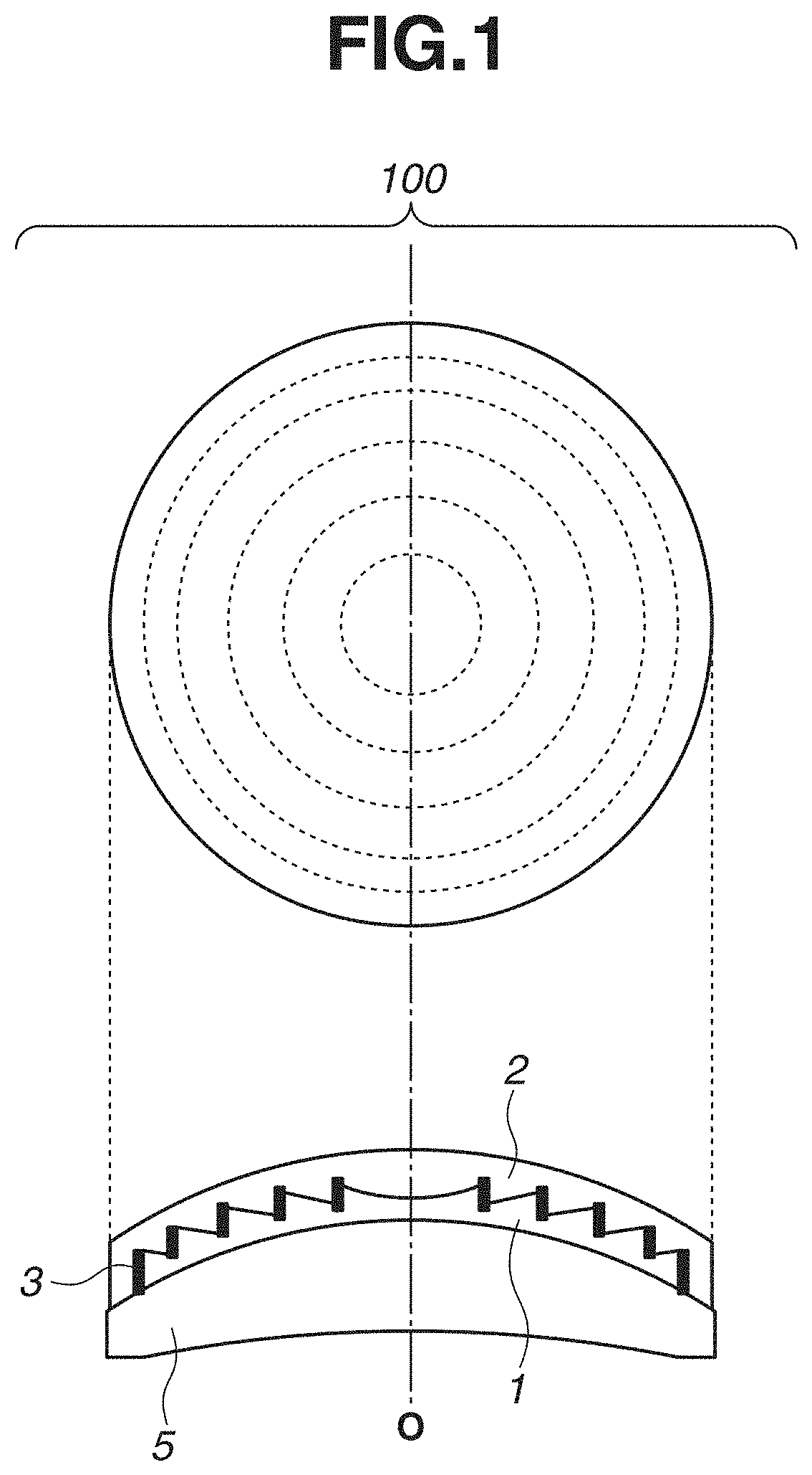
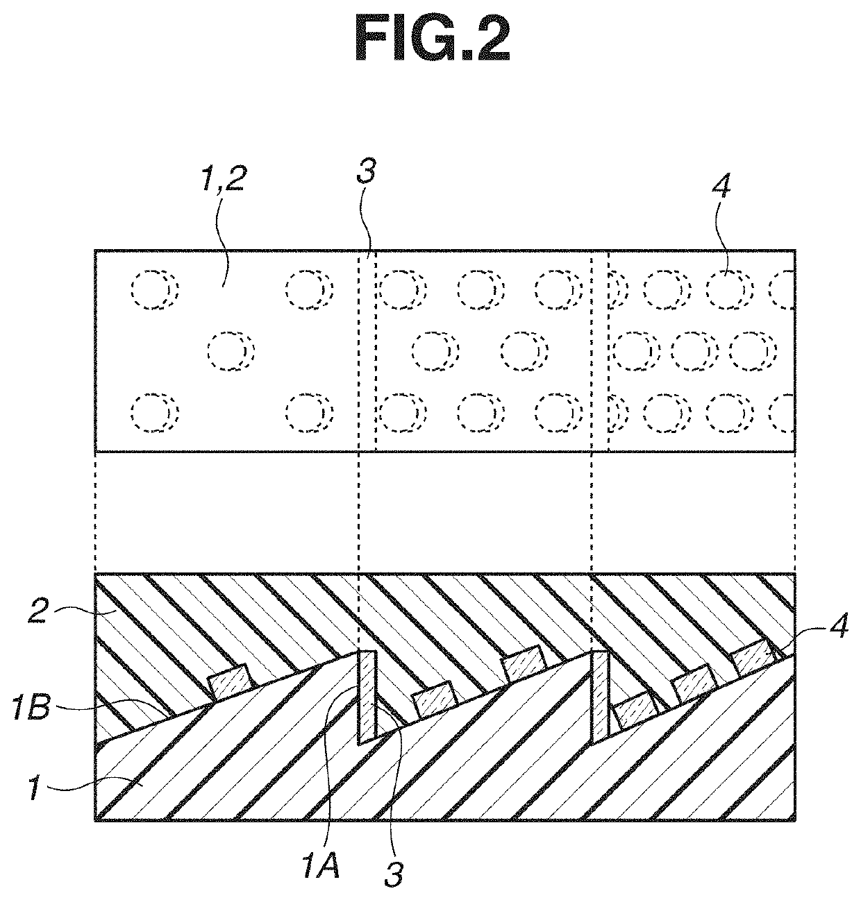
[0015]FIG. 1 is a top view and a side view illustrating a diffractive optical element according to an exemplary embodiment of the present disclosure. FIG. 2 is a partial enlarged view illustrating the diffractive optical element illustrated in FIG. 1.
[0016]A diffractive optical element 100 is composed of a first resin layer 1 having a diffraction grating shape and a second resin layer 2 stacked in this order in close contact on a first substrate 5. The diffraction grating shape is composed of a plurality of wall surfaces 1A and a plurality of slopes 1B. A high refractive-index portion 3 is formed on the wall surface 1A. The high refractive-index portion 3 has a higher refractive index than the first resin layer 1 and the second resin layer 2.
[0017]The first substrate 5 is a transparent substrate. For example, S-LAH55 (Ohara Inc.) as high-refractive-index low-dispersion glass of the lanthanum system and S-FPL51 (Ohara Inc.) as super-low-dispersion glass can be used. Although, in FIG....
PUM
 Abstract
Description
Claims
Application Information