Lightning protection system for a wind turbine blade

a protection system and wind turbine technology, applied in the field of rotor blades, can solve the problems of limiting the size and thereby the insulation strength, further restricting the size and geometry of the insulated lightning protection tip part, and restricting the insulation volume and/or material

Active Publication Date: 2020-02-20
SIEMENS GAMESA RENEWABLE ENERGY AS
View PDF0 Cites 7 Cited by
  • Summary
  • Abstract
  • Description
  • Claims
  • Application Information

AI Technical Summary

Problems solved by technology

This puts limitations to the size, and thereby the insulation strength, of the internal down conductor insulation required in the tip section of the lightning protection system.
Furthermore, for blades casted using the integral blade process, the manufacturing method further puts restrictions on the size and geometry of the insulated lightning protection tip part due to the mandrels and vacuum bags required for the process.
In addition to this, the insulation of the lightning protection tip part should only introduce a limited increase in total mass of the blade tip, which restricts the insulation volume and / or material.
Therefore, in practice, it is oftentimes sufficient to only provide, in the inboard section of the rotor blade, a low voltage insulation (or even no specific insulation) for the internal down conductor.
In this manufacturing process, the fiber-reinforced laminate material of the blade shell is not yet stiff and rigid when the two half shells are brought together, as the resin has not yet been injected and, even if some parts of the fiber-reinforced laminate material are pre-impregnated by resin, the resin is in any case not yet cured.

Method used


Image

  • Lightning protection system for a wind turbine blade
  • Lightning protection system for a wind turbine blade
  • Lightning protection system for a wind turbine blade

Examples


Embodiment Construction

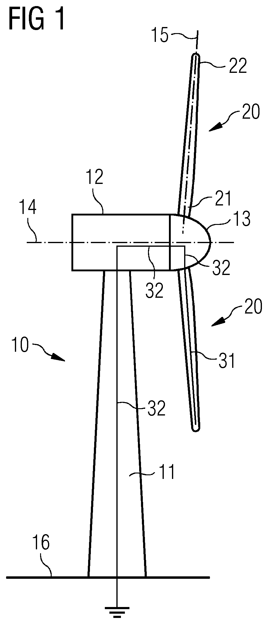
[0046]FIG. 1 shows a wind turbine 10 for generating electricity. The wind turbine 10 comprises a tower 11. The tower 11 comprises one end by which the tower 11 is connected to the ground 16 and another, opposite end, by which the tower 11 is connected to a nacelle 12 of the wind turbine 10. The nacelle 12 is rotatable mounted with regard to the tower 11. This enables a yaw movement of the nacelle 12 with respect to the tower 11. The nacelle 12 accommodates the generator of the wind turbine and further components of the wind turbine 10. If the wind turbine is a geared wind turbine, the nacelle 12 also may comprise a gear box.

[0047]The wind turbine 10 furthermore comprises a rotor which is arranged rotatable with respect to the nacelle 12. The rotor can thus be rotated about a rotor axis 14 which is located substantially horizontal with regards to the ground 16. The rotor of the wind turbine is destined to capture the energy of the wind, transform this energy into a rotational movemen...


PUM

PropertyMeasurementUnit
lengthaaaaaaaaaa
electricallyaaaaaaaaaa
areaaaaaaaaaaa

Abstract

Provided is a rotor blade of a wind turbine, wherein the rotor blade includes a trailing edge section with a trailing edge and a leading-edge section with a leading-edge, a root section with a root and a tip section with a tip, a shell which defines the outer shape of the rotor blade and a cavity which is confined by the shell, and a lightning protection system with an internal down conductor extending from the root section of the rotor blade to the tip section of the rotor blade, wherein the internal down conductor is connectable at the root section to a grounding system of the remainder of the wind turbine and at the tip section to at least one tip lightning receptor which is positioned at the surface of the rotor blade. In addition, the rotor blade comprises an electrically insulating tip part.

Description

CROSS-REFERENCE TO RELATED APPLICATIONS[0001]This application claims priority to PCT Application No. PCT / EP2018 / 052365, having a filing date of Jan. 31, 2018, which is based on German Application No. 10 2017 207 820.0, having a filing date of May 9, 2017, the entire contents both of which are hereby incorporated by reference.FIELD OF TECHNOLOGY[0002]The following relates to a rotor blade of a wind turbine with an improved lightning protection system. The following also relates to a method of manufacturing such a rotor blade and to a wind turbine comprising at least one such rotor blade.BACKGROUND[0003]Wind turbine blades are the most exposed parts of the wind turbine with respect to lightning strikes. Therefore, it is critical that the lightning protection system of a wind turbine blade is properly designed to protect the blade from damage in the event of a lightning strike. This is conventionally done by having an internal down conductor in the blade, which is connected to a ground...

Claims


Application Information

Patent Timeline
Patent Type & Authority Applications(United States)
IPC IPC(8): F03D80/30F03D1/06B29C70/48B29C70/72
CPCB29C70/48B29K2675/00F03D80/30F03D1/0675B29C70/72B29L2031/085F05B2230/50F05B2230/00B29D99/0025Y02E10/72Y02P70/50F05B2240/307
Inventor CHRISTIANSEN, THOMAS LEHRMANN
Owner SIEMENS GAMESA RENEWABLE ENERGY AS
Why Eureka
Try Eureka