
Method of determining an uncertainty estimate of an estimated velocity

a technology of uncertainty estimation and estimated velocity, which is applied in the direction of knowledge representation, instruments, and reradiation, can solve the problems of high uncertainty, estimation error, and inability to accurately estimate the velocity of surrounding objects, so as to improve the accuracy of uncertainty estimation and improve the accuracy of uncertainty measur

Active Publication Date: 2020-02-20
APTIV TECH LTD
View PDF0 Cites 8 Cited by
  • Summary
  • Abstract
  • Description
  • Claims
  • Application Information

AI Technical Summary

Benefits of technology

The patent text describes a system for automotive applications that uses sensor technology to determine the velocity and motion characteristics of objects in the vicinity of a host vehicle. This information helps the control unit of the host vehicle to securely control the vehicle and safely navigate through the environment. The text also mentions that uncertainty estimates can be used to track and classify objects, as well as improve the reliability and accuracy of applications like distance control and valet parking. The technical effect of this system is to enable secure and efficient autonomous or automated driving of the host vehicle.

Problems solved by technology

In general, the higher the potential error between the estimated and the true velocity, the higher the uncertainty.
However, as indicated above, a totally precise estimation of the velocities of surrounding objects is usually not possible.
An important motion characteristic is the velocity of a given object, which usually needs to be estimated by the host vehicle by means of sensors and is therefore subject to an estimation error, i.e. the estimated velocity deviates from the true velocity of the object.
Due to the inherent limitations of obtaining precise estimated velocities with modern sensor technology, in particular radar technology, there is the need to obtain knowledge about the potential error of an estimated velocity.

Method used


Image

  • Method of determining an uncertainty estimate of an estimated velocity
  • Method of determining an uncertainty estimate of an estimated velocity
  • Method of determining an uncertainty estimate of an estimated velocity

Examples


Embodiment Construction

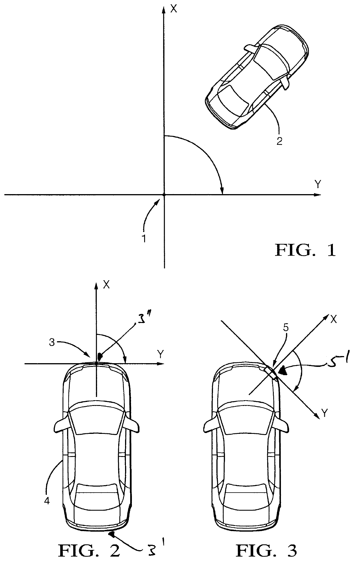
[0055]Generally, a host vehicle 4 (see FIG. 2) is equipped with a radar system 5′ (see FIG. 2) where reflected radar signals from a target 2 (FIG. 1) in the field of view of the radar system 5′ are processed to provide data in order to ascertain parameters used in the methodology.

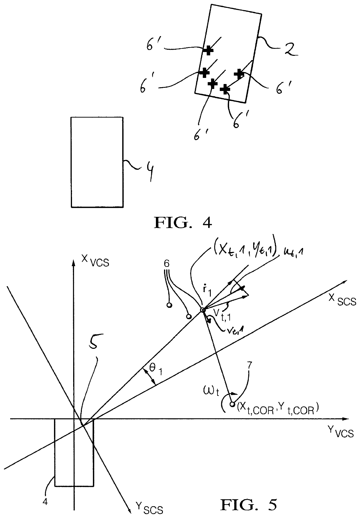
[0056]In order to do this various conditions and requirements may be of advantage. The target 2 (rigid body, e.g. vehicle) is preferably an extended target, i.e., the target allows the determination of a plurality of points of reflection 6′ (see FIG. 4) that are reflected from the target 2 in real-time and that are based on raw radar detection measurements.

[0057]The target 2 is an example of an object in the sense of the general part of the description and the claims. However, other types of objects are also possible, in particular objects that appear in ordinary traffic scenes, like motorcycles, bicycles, pedestrians, large as well as small vehicles. Moreover, in principal objects can also be stationary ob...


PUM


Abstract

A method of determining an uncertainty estimate of an estimated velocity of an object includes, determining the uncertainty with respect to a first estimated coefficient and a second estimated coefficient of the velocity profile equation of the object. The first estimated coefficient being assigned to a first spatial dimension of the estimated velocity and the second estimated coefficient being assigned to a second spatial dimension of the estimated velocity. The velocity profile equation represents the estimated velocity in dependence of the first estimated coefficient and the second estimated coefficient. The method also includes determining the uncertainty with respect to an angular velocity of the object, a first coordinate of the object in the second spatial dimension, and a second coordinate of the object in the first spatial dimension.

Description

CROSS-REFERENCE TO RELATED APPLICATION[0001]This application claims the benefit under 35 U.S.C. § 119(a) of European Patent Application EP 18189410.6, filed Aug. 16, 2018, the entire disclosure of which is hereby incorporated herein by reference.TECHNICAL FIELD OF INVENTION[0002]The invention relates to a method of determining an uncertainty estimate of an estimated velocity of an object, wherein the uncertainty estimate represents an uncertainty of the estimated velocity with respect to a true velocity of the object.BACKGROUND OF INVENTION[0003]Uncertainty estimates are useful for quantifying the validity of an estimated velocity. In other words, an uncertainty measure represents the extent to which an estimated velocity can be trusted, or the probability that the estimated velocity matches the true velocity. This is, the uncertainty can be interpreted as the range of potential error between the true and the estimated velocity. According to one definition the uncertainty represents...

Claims


Application Information

Patent Timeline
Patent Type & Authority Applications(United States)
IPC IPC(8): G01P3/66G06N5/02G06F17/16
CPCG01P3/665G06N5/022G06F17/16G01P21/02G01S13/581G01S13/60G01S7/40G01S7/2921G01S7/2955G01S13/42G01S13/584G01S13/589G01S13/726G01S13/931G01S2013/93274G01S2013/93271G01S2013/932
Inventor STACHNIK, MATEUSZCIESLAR, DARIUSZ
Owner APTIV TECH LTD
Learn More