
Multifunctional high-voltage connector and battery product

Active Publication Date: 2020-02-20
CONTEMPORARY AMPEREX TECH CO
View PDF2 Cites 7 Cited by
  • Summary
  • Abstract
  • Description
  • Claims
  • Application Information

AI Technical Summary

Benefits of technology

The present invention provides a multifunctional high-voltage connector and battery product. This connector integrates the functions of different connectors, which reduces battery product space occupancy and improves its integration. The conductive connection structure simultaneously connects with two mating terminals, allowing the battery to turn on or off depending on the need for maintenance. The multifunctional high-voltage connector combines both a switch function and a high-voltage connection function, with the connection resistance being greatly reduced. The integration of the battery product and the external device is facilitated through the harness assembly of the multifunctional high-voltage connector.

Problems solved by technology

Because the existing three types of connectors are independent components, when at least above two types of connectors are required based on the using requirements of the battery product, the following problems will occur: (1) the two types of connectors need to be connected by an adapter sheet, thereby increasing the connection resistance in the battery product; (2) different holes need to be provide on the box of the battery product to respectively mount the different connectors, which is not beneficial to the integration of the battery product; (3) because the number of the holes provided on the box of the battery product is more, which increases the interfaces to be sealed, thereby reducing the sealing reliability of the battery product; (4) the multiple types of connectors are simultaneously arranged, which increases the mounting space of the battery product.

Method used


Image

  • Multifunctional high-voltage connector and battery product
  • Multifunctional high-voltage connector and battery product
  • Multifunctional high-voltage connector and battery product

Examples


Embodiment Construction

[0101]Hereinafter a multifunctional high-voltage connector and a battery product according to the present disclosure will be described in detail in combination with the figures.

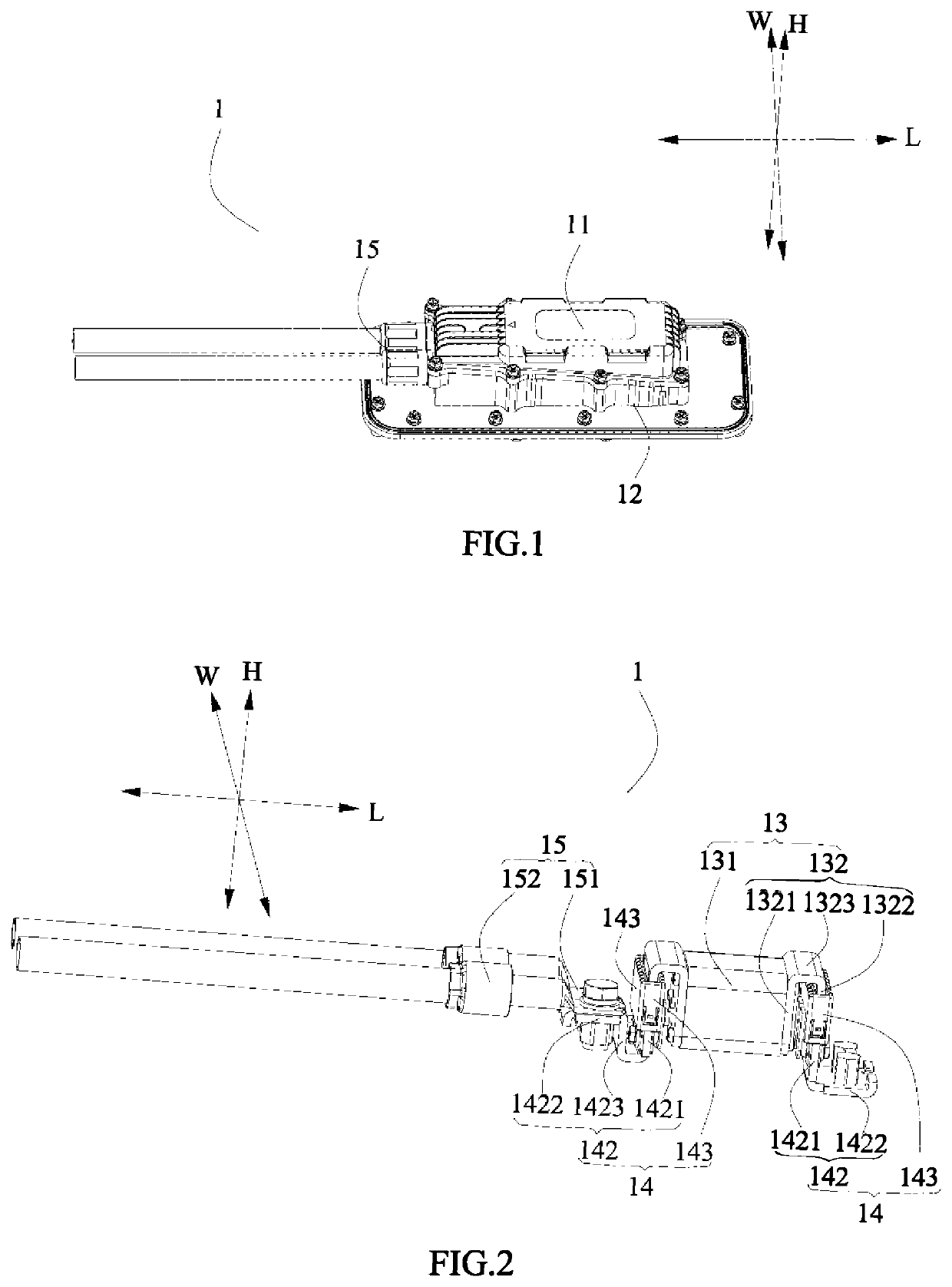
[0102]A battery product according to the present disclosure comprises a battery assembly (not shown), a box (not shown) and a multifunctional high-voltage connector 1. The battery assembly is accommodated in the box and comprises a plurality of batteries, the multifunctional high-voltage connector 1 is fixedly mounted to the box and electrically connected to the battery assembly.

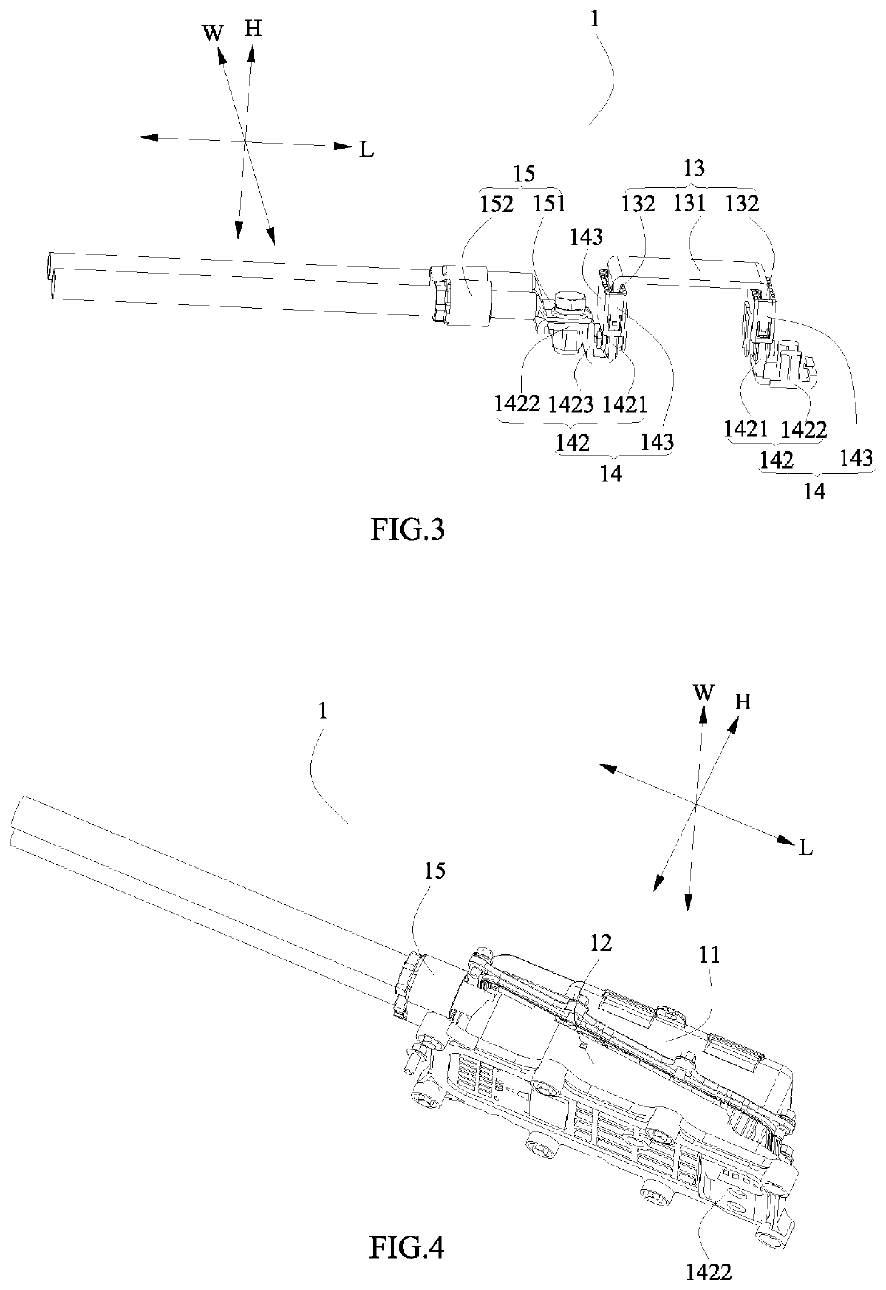
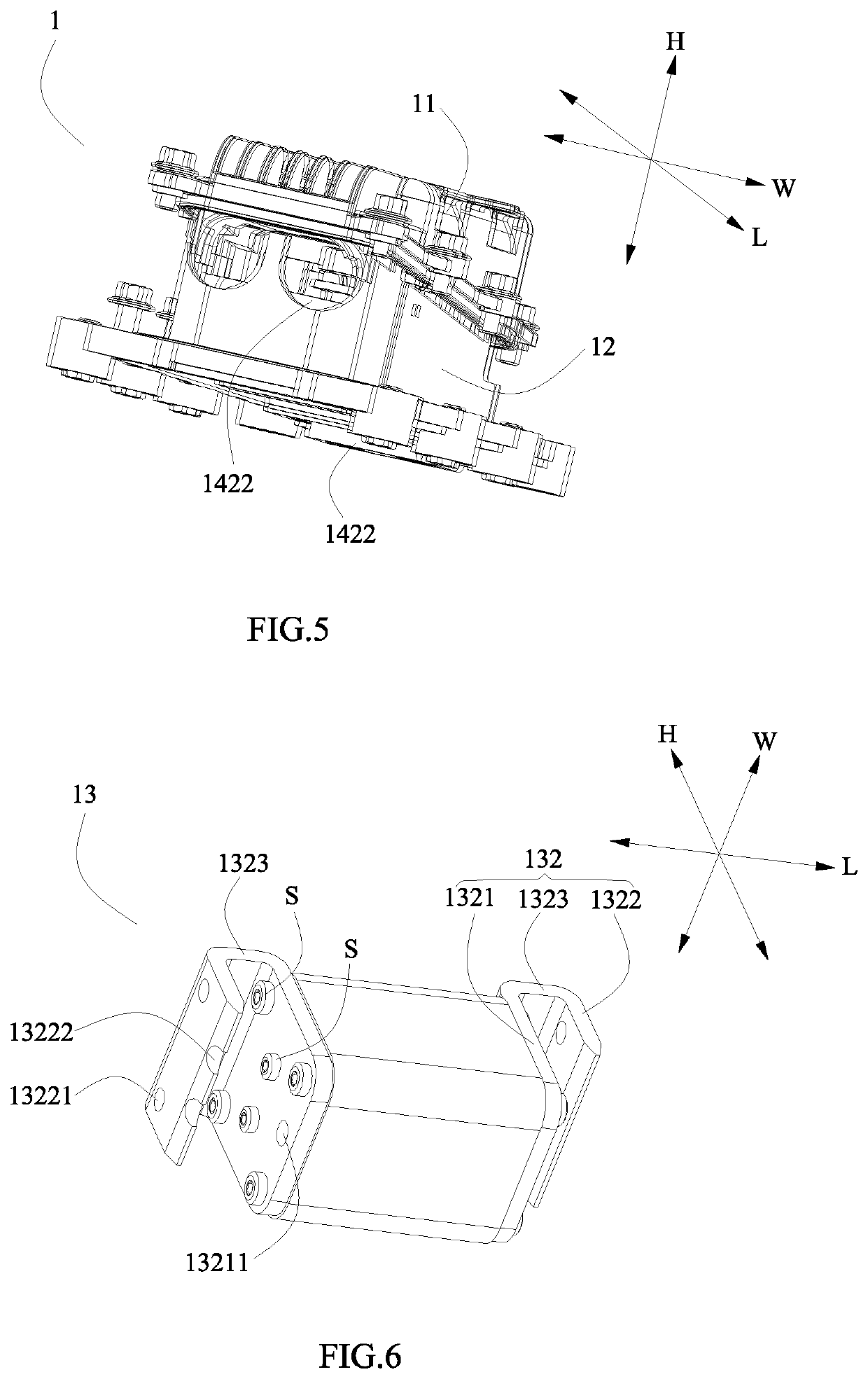
[0103]Referring to FIG. 1 to FIG. 4, the multifunctional high-voltage connector 1 may comprise an upper cover 11, a pedestal 12, a conductive connection structure 13, two mating terminals 14 and a harness assembly 15. The upper cover 11 and the pedestal 12 are detachably assembled. The conductive connection structure 13 is fixedly mounted to the upper cover 11. The two mating terminals 14 are spaced apart from each other in a length d...


PUM


Abstract

The present disclosure provides a multifunctional high-voltage connector and a battery product, the multifunctional high-voltage connector comprises: an upper cover; a pedestal; a conductive connection structure; two mating terminals; and a harness assembly. The conductive connection structure is used to make the two mating terminals be connected in series, and the harness assembly is directly connected to one of the mating terminals. When the upper cover and the pedestal are assembled, the conductive connection structure is simultaneously in contact with the two mating terminals, thereby turning on the high-voltage circuit. When the battery product requires maintenance, the upper cover is directly detached from the base, thereby turning off the high-voltage circuit. The battery product can be electrically connected to an external device via the harness assembly. The multifunctional high-voltage connector integrates both a switch function and a high-voltage connection function, therefore the connection resistance is greatly reduced.

Description

CROSS-REFERENCE TO RELATED APPLICATIONS[0001]The present application claims priority to Chinese patent application No. CN201821317464.5, filed on Aug. 15, 2018, which is incorporated herein by reference in its entirety.FIELD OF THE PRESENT DISCLOSURE[0002]The present disclosure relates to the field of connector technology, and particularly relates to a multifunctional high-voltage connector and a battery product.BACKGROUND OF THE PRESENT DISCLOSURE[0003]In the battery product (such as a battery pack or a high-voltage cartridge), the common types of connectors generally include: high-voltage connector, Manual Service Disconnect (MSD), and fuse. The high-voltage connector is used for realizing electrical connection between the battery product and an external device (such as another battery pack or another high-voltage cartridge), the MSD is used for controlling the operation of turning on or turning off the high-voltage circuit of the battery product, and the fuse is used for providin...

Claims


Application Information

Patent Timeline
IPC IPC(8): H01R11/28H01R11/01H01R31/06H01R13/68H01R13/703H01M2/34H01M2/20H01M50/503H01M50/51
CPCH01R11/287H01R31/065H01M2/202H01R11/01H01M2200/103H01R13/7031H01R13/68H01M2/348H01H2085/025H01H2009/108H01R13/5213Y02E60/10H01M50/51H01M50/503H01M50/581H01M50/502
Inventor LI, JIANWEIBAO, CONGYANG, MINGPINGCHAN, LIBINGZHOU, LINGGANG
Owner CONTEMPORARY AMPEREX TECH CO
Learn More