Gas permeable flowerpot

a flowerpot and gas-permeable technology, applied in the field of flowerpots, can solve the problems of plants drying up, difficult for the current flower pots to make the soil gas-permeable, and maintain the soil at a certain degree of wetness, so as to prevent plants from dying, improve the absorption of gaseous pollutants by plants, and improve the ambient air quality

Inactive Publication Date: 2020-02-27
RENCHSAND ECO ENVIRONMENT PROTECTION SCI & TECH CO LTD
View PDF0 Cites 0 Cited by
  • Summary
  • Abstract
  • Description
  • Claims
  • Application Information

AI Technical Summary

Benefits of technology

[0007]In view of this, it is necessary to provide a gas permeable flowerpot which can prevent roots of potted plants from being eroded and can retain water for the potted plants. A gas permeable flowerpot comprises a tray, a flowerpot body, and a bottom plate. The tray comprises an accommodating trough for accumulating water; the flowerpot body is provided with a plurality of stacked hollow subunits which are filled with soil; each of the hollow subunits comprises an upper edge and a lower edge respectively at two ends; a lower edge of a hollow subunit in an upper layer of adjacent hollow subunits is positioned lower than an upper edge of a hollow subunit in a lower layer of the adjacent hollow subunits, and the lower edge of the hollow subunit in the upper layer is closer to a centerline of the flowerpot body than the upper edge of the hollow subunit in the lower layer so that a gap is formed between said lower edge and said upper edge; the bottom plate is made of a micro-porous water absorbing material and comprises a water permeable plate and water absorbing column which extends downwardly out from the water permeable plate; the soil is in contact with the water permeable plate, and the water absorbing column extends downwardly into the accommodating trough.
[0008]Compared with the prior art, in the gas permeable flowerpot provided by an embodiment of the present invention, on one hand, a lower edge of a hollow subunit in an upper layer of adjacent hollow subunits is positioned lower than an upper edge of a hollow subunit in a lower layer of the adjacent hollow subunits so that a gap is formed between said lower edge and said upper edge, and water can be prevented from flowing out of the gap when the potted plants are watered, and water flows from the hollow subunit in the upper layer (and the soil therein) to the hollow subunit in the lower layer (and the soil therein) and finally flows into the accommodating trough, thereby preventing the root erosion of the potted plants and increasing the contact of the soil at the edge of each layer with the air, that is, increasing the gas permeability of soil at each layer; on the other hand, the water permeable plate contacts the soil (and the roots of the plants), and the water absorbing column extends into the accumulated water in the flowerpot body and therefore can upwardly absorb and continuously supplement the soil and roots with moisture to prevent the plants from dying for drought. The moist potting soil can absorb the pollution gas such as formaldehyde in the air, thereby maximally improving the plant's absorption of gaseous pollutants and improving the ambient air quality.

Problems solved by technology

However, the inventors of the present invention found that the moist potting soil can adsorb the pollution gas such as formaldehyde in the air, and therefore keeping the potting soil well ventilated and maintaining a certain degree of wetness are important for the plant to absorb indoor air pollutants; however, it is hard for the current flower pots to make the soil gas permeable and maintain the soil at a certain degree of wetness.
People always water too much to cause erosion of roots or forget to water the plants to cause the plants to dry up, which is very inconvenient.

Method used


Image

  • Gas permeable flowerpot
  • Gas permeable flowerpot
  • Gas permeable flowerpot

Examples


first embodiment

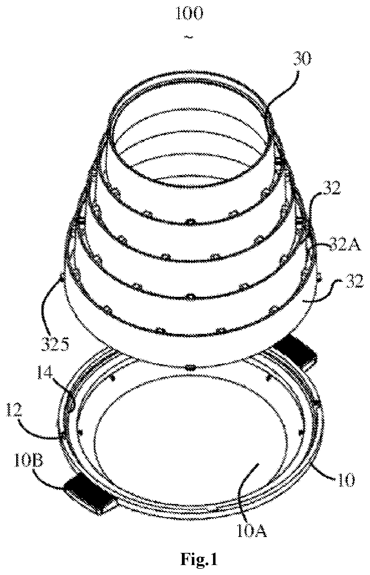
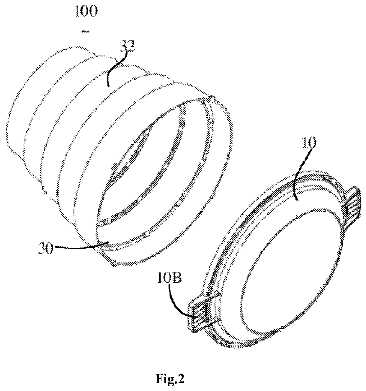
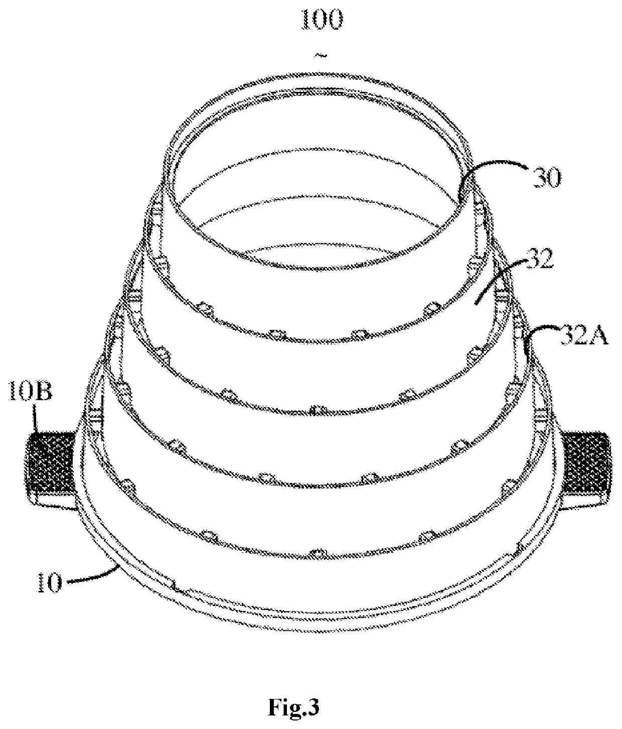
[0020]Referring to FIGS. 1-4, the present invention provides a gas permeable flowerpot 100, comprising a tray 10, a flowerpot body 30, and a bottom plate 50.

[0021]The tray 10 has a round tray and comprises an accommodating trough (10A) for accumulating water. In this embodiment, the tray 10 further comprises left and right handles 10B extending from the lateral edges so that people can hold the handles 10B to move the flowerpot 100 and place it in different positions, such as a window sill, a balcony and the like. Each of the handles 10B also has a rough surface for the anti-slip purpose. In this embodiment, the tray 10 is made of a transparent material, such as glass, to facilitate the user to view the water accumulated therein to determine whether or not to water the potted plants, thereby preventing the plants from drying out. In other modified embodiments, the tray 10 may be made of other materials, for example transparent plastics, such as polymethyl methacrylate (acrylic), and...

second embodiment

[0034]Referring to FIG. 7 and FIG. 8, the present invention provides a gas permeable flowerpot 200, comprising a tray 210, a flowerpot body 230, and a bottom plate (not shown).

[0035]The gas permeable flowerpot 200 is similar in structure to the gas permeable flowerpot 100 provided in the first embodiment, except that the outer contour of each hollow subunit 232 is in the shape of an inverted circular truncated cone and the hollow subunits are stacked up to form the flowerpot body 230 and the adjacent hollow subunits 232 are integrally connected by reinforcing ribs 270. The flowerpot body 230 is formed by fastening a plurality of hollow subunits 233 by snaps or screws, and has a cylindrical outer contour as a whole.

[0036]In addition, as shown in FIG. 7, four projections 2325 are arranged on a lower edge of a hollow subunit 232 at the bottom, i.e., the hollow subunit 232 closest to the tray 210; correspondingly, the inner edge of the tray 10 is provided with four guiding grooves 212 a...


PUM


Abstract

A gas permeable flowerpot (100), comprising: a tray (10), a flowerpot body (30), and a bottom plate (50). The tray (10) comprises an accommodating trough (10A) for accumulating water; the flowerpot body (30) is filled with soil; the flowerpot body (30) is provided with a plurality of stacked hollow subunits (32); the soil in each hollow subunit (32) is gas permeable; the bottom plate (50) is made of a micro-porous water absorbing material and comprises a water permeable plate (51) and a water absorbing column (52) which extends downwardly out from the water permeable plate (51); the soil is in contact with the water permeable plate (51), and the water absorbing column (52) extends into the accommodating trough (10A). Because of the water permeability of the water permeable plate (51), excessive water can flow through the water permeable plate (51) into the tray (10) to prevent roots from being eroded by water. In addition, the water absorbing column (52) extends into the tray (10) to upwardly absorb and continuously supplement the soil and roots with moisture.

Description

TECHNICAL FIELD[0001]The present invention relates to flowerpots, in particular to a gas permeable flowerpot which can prevent roots of potted plants from being eroded and can retain water for the potted plants.[0002]BACKGROUND ART[0003]In recent years, due to increased air pollution, people's requirements for the air quality of living spaces have become higher and higher.[0004]Studies have shown that indoor air pollutants mainly include the following six types of pollutants, including benzene, formaldehyde, phthalates, trichloroethylene, toluene and ammonia. At present, in domestic civil building standards, the indoor formaldehyde content should not be higher than 0.08 mg per cubic meter, the indoor benzene content should not be higher than 0.09 mg per cubic meter, and the indoor ammonia content should not be higher than 0.2 mg per cubic meter.[0005]In order to improve the air quality, people have moved various kinds of plants into rooms, plants such as tigertail orchid, monstera, ...

Claims


Application Information

Patent Timeline
Patent Type & Authority Applications(United States)
IPC IPC(8): A01G9/04A01G9/02
CPCA01G2009/003A01G9/042A01G9/02A01G9/028A01G27/06
Inventor QIN, SHENGYI
Owner RENCHSAND ECO ENVIRONMENT PROTECTION SCI & TECH CO LTD
Why Eureka
Try Eureka