Device for measuring and/or stimulating brain activity
a brain activity and brain technology, applied in the field of brain activity measuring and/or stimulating brain activity, can solve the problems of limiting use, difficult handling of devices, and inseparable us
- Summary
- Abstract
- Description
- Claims
- Application Information
AI Technical Summary
Benefits of technology
Problems solved by technology
Method used
Image
Examples
first embodiment
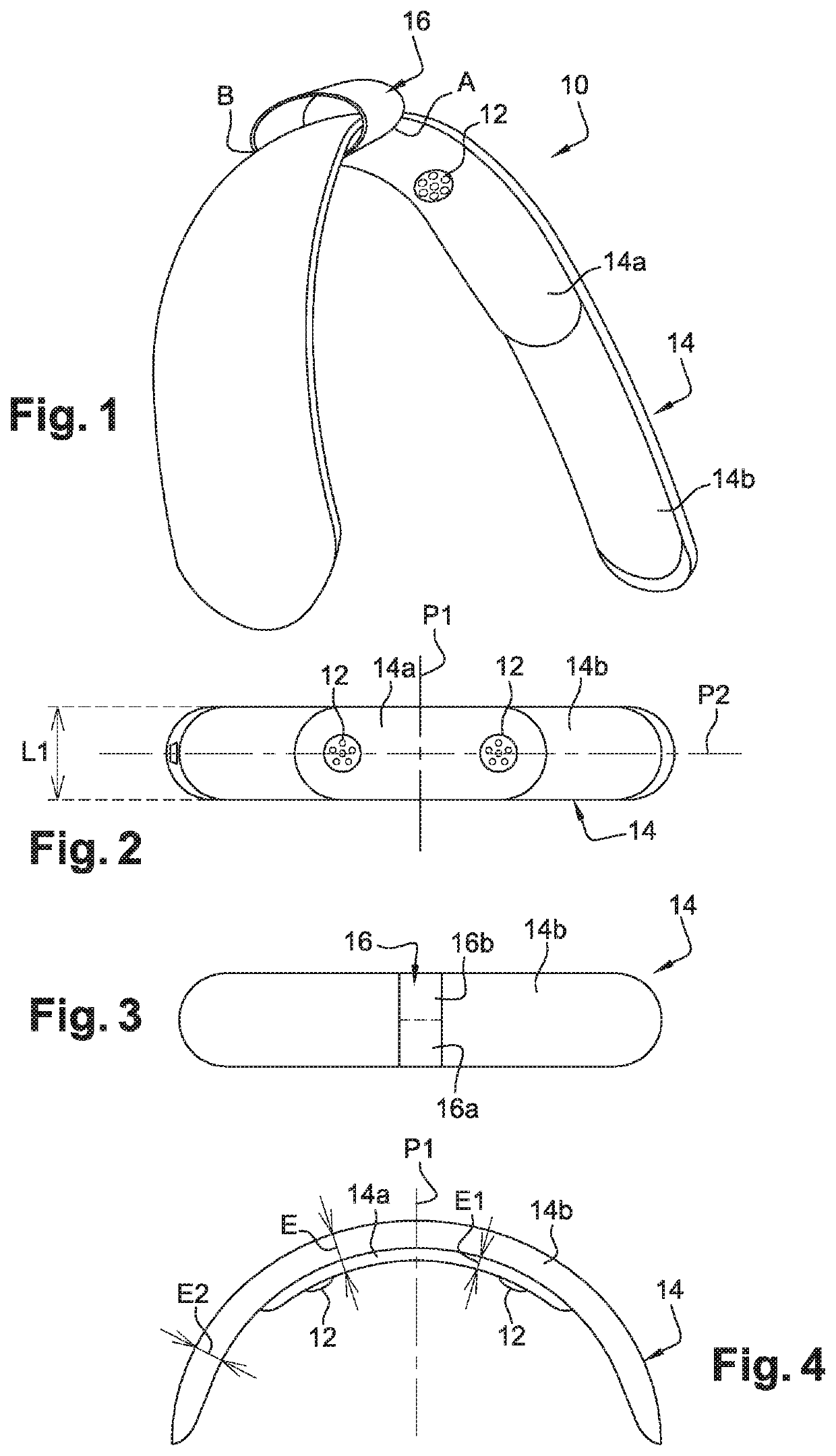
[0085]FIGS. 1 to 4 represent a device 10 according to the invention of measuring an individual's brain activity. In this embodiment, the device 10 measures the electrical brain activity (EEG) of the individual who wears it.
[0086]According to this embodiment, the device 10 essentially includes:[0087]transmitting and / or detecting means 12, in this case sensors 12 for detecting electrical signals transmitted by the individual's brain,[0088]a support 14 for sensors 12, and[0089]means 16 for removably attaching the support to an accessory intended to be worn by the individual on his or her head, such as a headset (FIGS. 9a and 9b).
[0090]Sensors 12 will be described in detail in the following with reference to FIGS. 10a 10c.
[0091]In this embodiment, the support 14 has a generally elongated and C or U curved shape. It is configured to extend to the top or even the sides of the individual's head. It includes here two curved parts 14a, 14b mounted one inside the other, or superposed.
[0092]I...
second embodiment
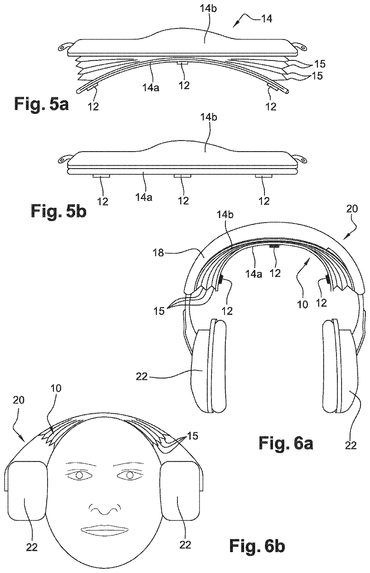
[0101]Thus, this second embodiment of the support 14 makes it possible to adapt the distance between the sensors and / or transmitters 12 and the head, and if necessary, to ensure that the pressure exerted on each of the sensors and / or transmitters 12 on the stimulation or measurement area is adequate. Indeed, part 14b (upper side) remains in contact with the accessory 20 following its curvature (see FIG. 6a), while part 14a (lower side) follows the curvature of the user's head (see FIG. 6b). The accordion shape of support 14 allows the device 10 to push in both directions: towards accessory 20 and towards the user's head.
[0102]In addition, the support 14 according to the second embodiment has two positions. A so-called closed position (see FIG. 5a), in which parts 14a and 14b are in contact over their entire length and an open position (see FIG. 5b), in which the longitudinal ends of parts 14a and 14b are spaced from each other. The closed position makes it easier to store and transp...
third embodiment
[0106]In the third embodiment, the device 10 is electronically autonomous but at least one of the electrodes 27 is integrated in the accessory 20, so it is necessary that the device 10 is attached and connected to the accessory 20 so that it can retrieve the signal from electrodes 27 and operate.
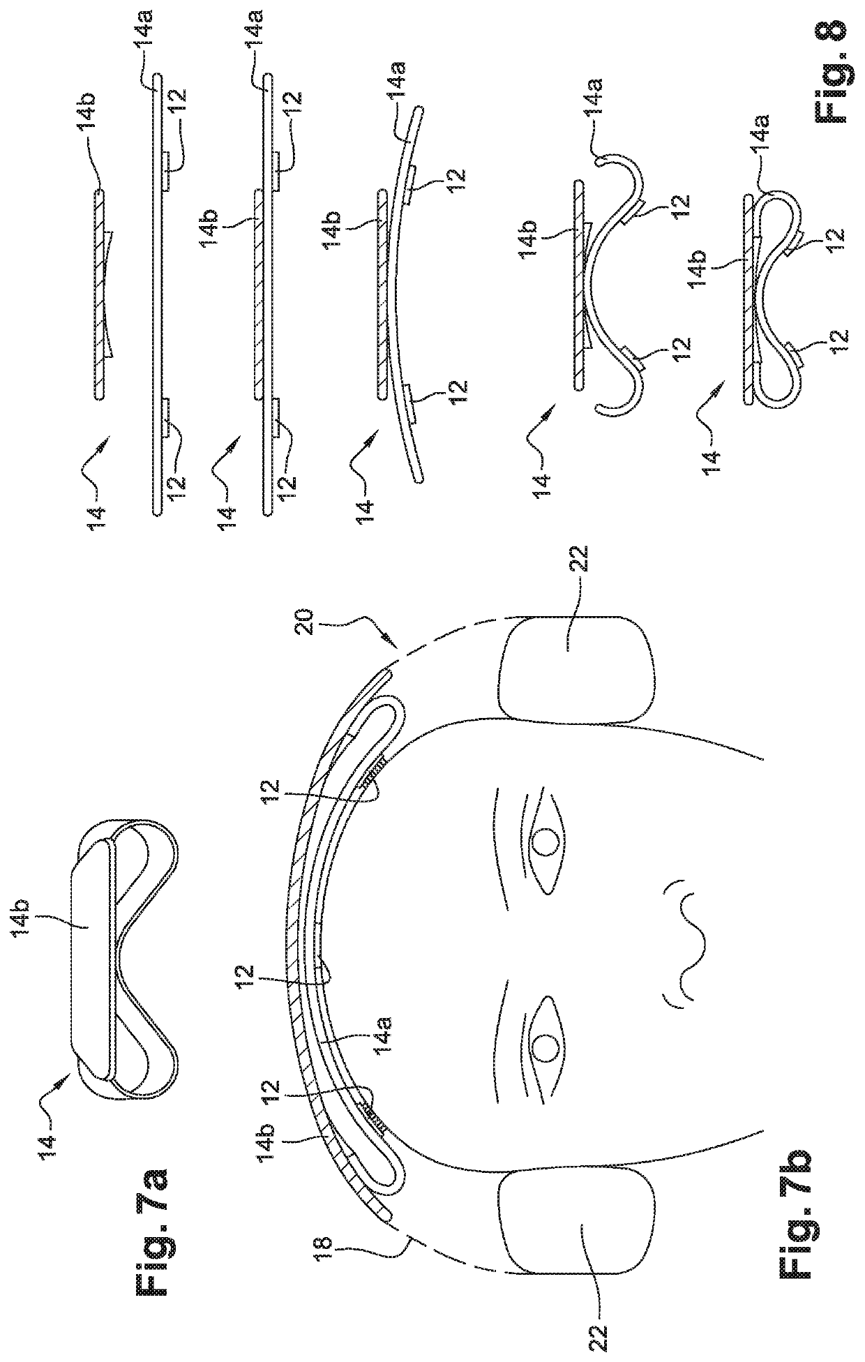
[0107]In general, the solution chosen to fill the gap between the user's scalp surface and the accessory 20 preferably has a flexibility that allows a certain elastic pressure to be applied to the sensors and / or transmitters 12 while allowing a so-called flat closure (or opening) of the support 14 adapted in particular to the storage of the device 10. The attaching means 16 are intended to secure the device to the accessory 20, for example to ensure optimal positioning of the device 10 on the head or to maintain it discreetly between the accessory 20 and the individual's head, especially when the accessory 20 is an audio headset, as shown in FIGS. 10a and 10b.
[0108]Attaching means 16 can be...
PUM
 Abstract
Description
Claims
Application Information
 - R&D
- Intellectual Property
- Life Sciences
- Materials
- Tech Scout
- Unparalleled Data Quality
- Higher Quality Content
- 60% Fewer Hallucinations
Browse by: Latest US Patents, China's latest patents, Technical Efficacy Thesaurus, Application Domain, Technology Topic, Popular Technical Reports.
© 2025 PatSnap. All rights reserved.Legal|Privacy policy|Modern Slavery Act Transparency Statement|Sitemap|About US| Contact US: help@patsnap.com


