Tdi line detector

Active Publication Date: 2020-02-27
DEUTSCHES ZENTRUM FUER LUFT & RAUMFAHRT EV
View PDF0 Cites 0 Cited by
  • Summary
  • Abstract
  • Description
  • Claims
  • Application Information

AI Technical Summary

Benefits of technology

The TDI line detector is a type of image sensor that uses multiple TDI lines to capture images. The detector is divided into sub modules, each with its own set of readout electronics. These electronics are positioned to match the length of the pixels. The TDI lines are activated synchronously and the detector is preferably embodied as a monolithic chip, more preferably using CMOS technology. The detector can provide high-resolution imaging by positioning the pixels of each sub module with pixel-level accuracy. Alternatively, the detector can provide improved signal-to-noise ratio by combining the pixel sizes on different lines. This design reduces the stability problem and the associated expense for the readout electronics and postprocessing.

Problems solved by technology

One problem in TDI line detectors with multiple TDI stages is the stability in order to limit the jitter between the pixels to less than ⅓ of a pixel during recording.
This particularly limits the desire for an increase in the number of lines.
But even with the conventional number of lines, this requires an increased complexity, for example because of so-called microvibrations in a satellite.

Method used


Image

  • Tdi line detector
  • Tdi line detector

Examples


Embodiment Construction

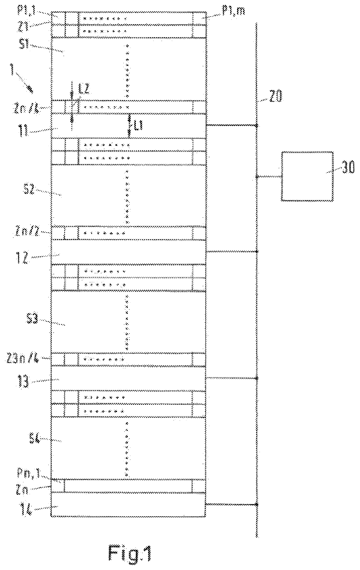
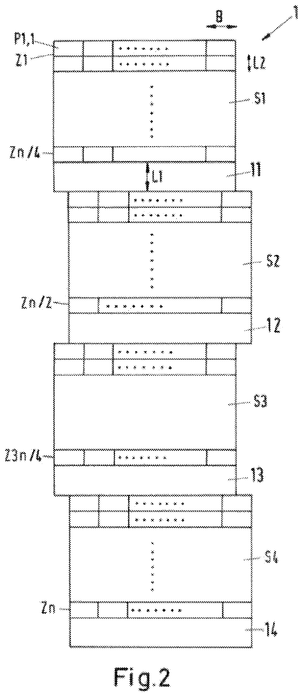
[0016]FIG. 1 schematically depicts a TDI line detector 1, which has a total of n lines Z with m pixels P. In this case, for example, P1,1 is the first pixel P of the first line, Z1 is the first line, and Zn is the nth line. The TDI line detector 1 in the example shown is divided into four submodules S1-S4, which each have n / 4 lines Z. The size of all of the pixels P is the same in all of the lines Z in all of the submodules S1-S4. The respective last line Z of a submodule S1-S4 is associated with a set of readout electronics 11-14 associated with the submodule S1-S4. The readout electronics 11-14 are embodied for example as shift registers and are connected via at least one bus system 20 to an evaluation unit 30. In this case, it is also possible for each set of readout electronics 11-14 to be connected via a separate bus system to the evaluation unit 30 or alternatively to a mass storage device.

[0017]The length L1 of the readout electronics 11-14 in this case is an integral multipl...


PUM


Abstract

The invention relates to a TDI line detector (1), comprising n TDI lines (Z1-Zn), wherein each TDI line (Z) has m pixels (P), and at least one read-out electronics (11-14), wherein the TDI line detector (1) is subdivided into x submodules (S1-S4), wherein the number of lines (Z) of a submodule (S1-S4) is n / x, wherein a discrete read-out electronics (11-14) is associated with the last line of each submodule (S1-S4), wherein the length (L1) of the read-out electronics (11-14) corresponds to an integer multiple of the length (L2) of a pixel (P), wherein x≥2 is, wherein the associated pixels (P) of different submodules (S1-S4) are arranged pixel to pixel relative to one another or the submodules (S1-S4) or groups of submodules (S1-S4) are laterally interlinked alternately by half a pixel (P).

Description

BACKGROUND OF THE INVENTION1. Field of the Invention[0001]The invention relates to a TDI line detector.[0002]Particularly in the field of earth observation, various methods and sensors are known that scan the earth from orbit with the aid of various sensors (lines or matrixes). Using various technologies, the aim is to maximize the resolution of the instrument both spectrally and geometrically. Examples of such technologies are sensor architectures with TDI line detectors or movement-compensated matrix detectors and / or line detectors.2. Brief Description of the Related Art[0003]DE 10 2008 024 417 B3 has disclosed a TDI line detector comprising n TDI lines, each TDI line having m pixels. In this case, at least one outer line is associated with a readout register unit, each pixel of the first and / or nth line being associated with a separate register. In it, a masking is provided between two pixels of each line, the masking having a width of one pixel or an integral multiple of one pix...

Claims


Application Information

Patent Timeline
IPC IPC(8): H01L27/148H04N5/372
CPCH04N5/37213H01L27/14856H04N25/711H04N25/713
Inventor ECKARDT, ANDREAS
Owner DEUTSCHES ZENTRUM FUER LUFT & RAUMFAHRT EV
Why Eureka
Try Eureka