
Method for manufacturing a patch equipped with a radiofrequency transponder and tire comprising such a patch

Active Publication Date: 2020-03-05
MICHELIN & CO CIE GEN DES ESTAB MICHELIN
View PDF0 Cites 13 Cited by
  • Summary
  • Abstract
  • Description
  • Claims
  • Application Information

AI Technical Summary

Benefits of technology

[0017]The production of this rubber patch in two operations allows the radio frequency transponder to be placed in the patch with a high precision and reproducibly. It is thus possible to place it optimally and reproducibly on the wall of a tyre.
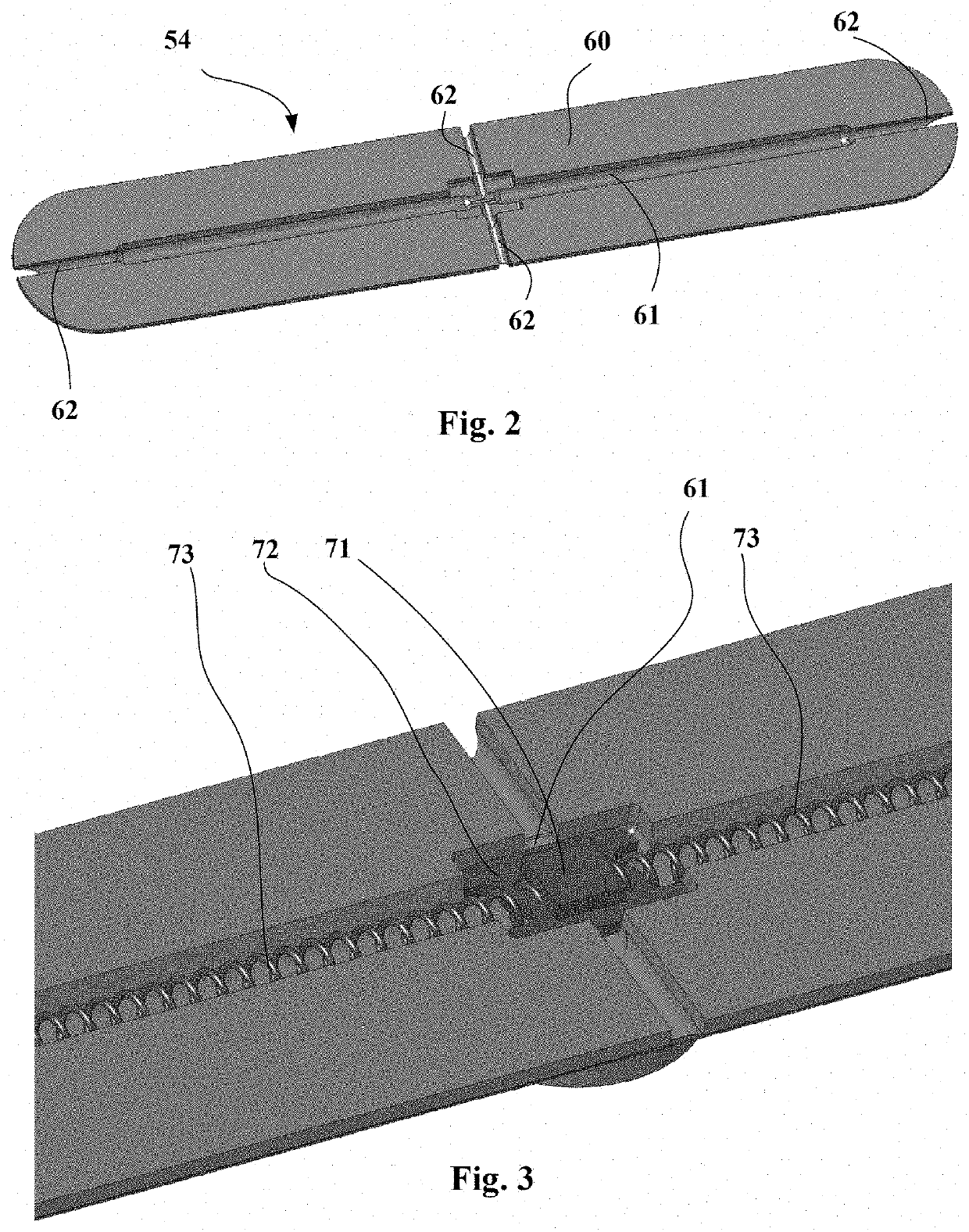
[0019]This groove placed facing a vent of the mould allows air to be evacuated from between the two rubber blends during the introduction of the second layer into the second mould or the closure of this second mould and thus bubbling defects in the final patch to be avoided.
[0025]According to another embodiment, after the vulcanized first layer has been obtained, this vulcanized first layer is placed in the impression of the second mould and the non-vulcanized rubber second layer is placed in the internal cavity of the second mould in a short time preferably shorter than one hour.
[0031]The advantage of an adhesive layer made of silanized polyether is that it allows a very wide temperature range of use to be achieved, i.e. one that covers both high and low temperatures.
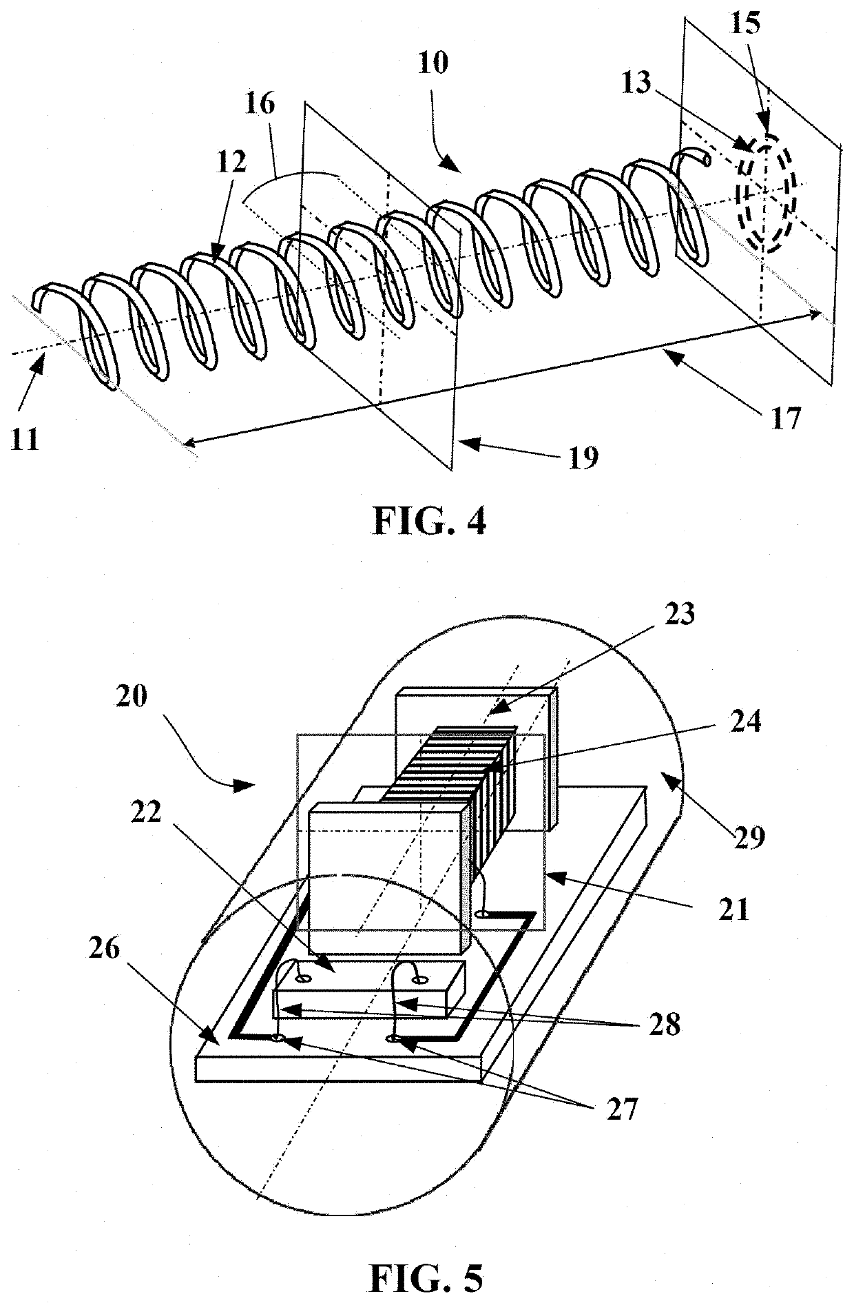
[0033]In particular, the communication frequency of the radiofrequency transponder is located in the ultra-high-frequency (UHF) band comprised between 300 MHz and 3 GHz, allowing an advantageous compromise to be obtained between the size of the radiating antenna, which may be small, allowing the antenna to be easily integrated into a rubber patch intended for a tyre casing, and the distance from which the radiofrequency transponder is readable, this distance possibly being far from the tyre casing. Advantageously, the radiofrequency transponder communicates in the narrow frequency band comprised between 860 MHz and 960 MHz and more specifically in the very narrow bands of 860 MHz to 870 MHz and 915 MHz to 925 MHz. Specifically, at these frequencies, for the conventional elastomer blends of tyre casings a good compromise is reached with respect to propagation of the electromagnetic waves. In addition, these frequencies are the highest possible in order to minimize the size of the radiating antenna and thus facilitate integration of the radio-frequency transponder embedded in a rubber patch into the tyre casing.
[0036]This second embodiment has the advantage of mechanically disassociating the radiating antenna from the electronic components of the transponder and thus of avoiding the weak point of conventional transponders, namely the zone in which the antenna segments are fastened to the carrier of the electronic chip.

Problems solved by technology

However, the drawback of such a process is that bubbles are generated in the interior of the patch, weakening it mechanically.

Method used


Image

  • Method for manufacturing a patch equipped with a radiofrequency transponder and tire comprising such a patch
  • Method for manufacturing a patch equipped with a radiofrequency transponder and tire comprising such a patch
  • Method for manufacturing a patch equipped with a radiofrequency transponder and tire comprising such a patch

Examples


Embodiment Construction

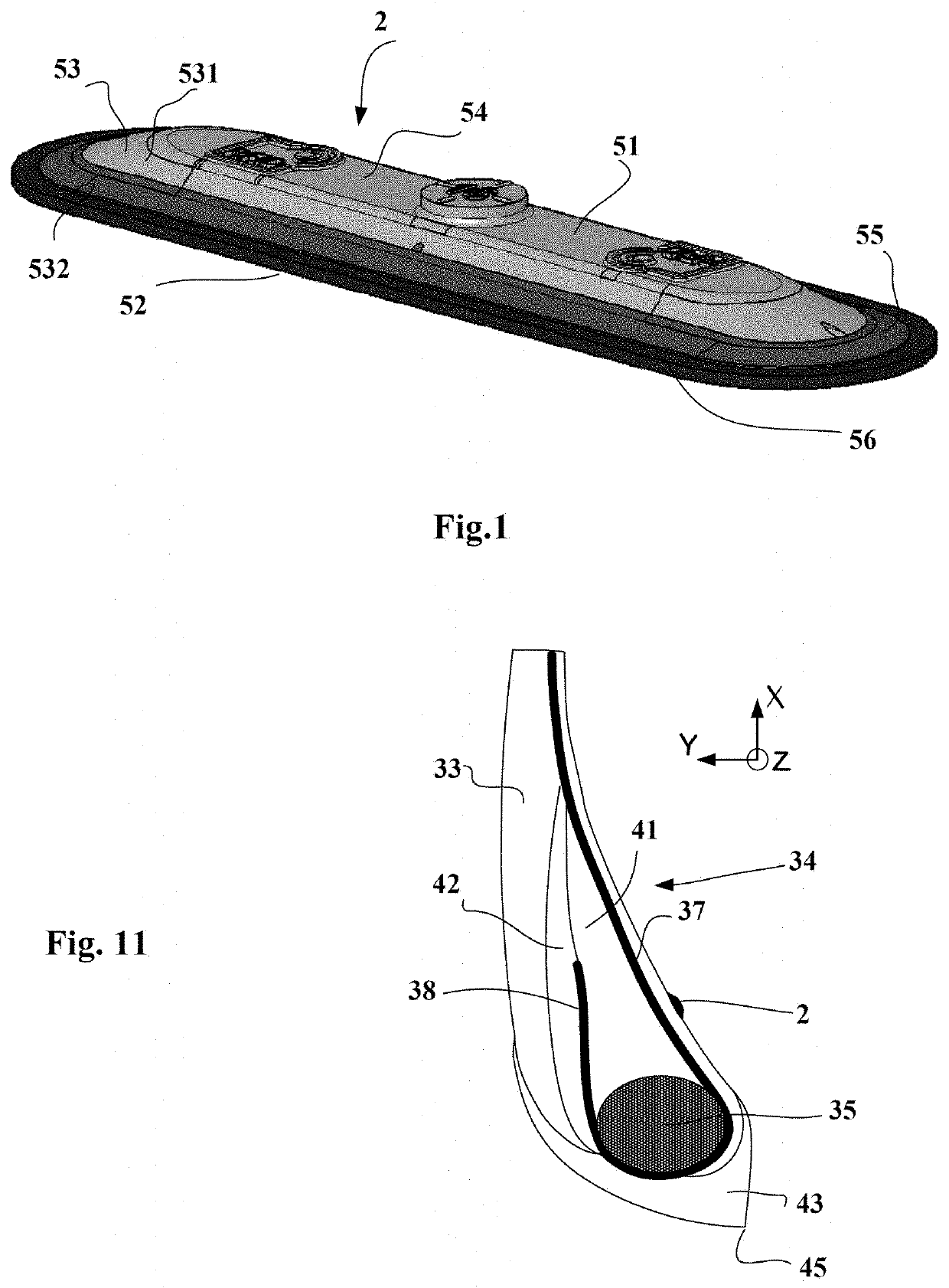
[0055]FIG. 1 is a perspective view of a patch 2 according to the invention.

[0056]This patch is of elongate shape and has a substantially planar upper surface 51, a substantially planar lower surface 52 intended to be fastened to the wall of a tyre, and a skirt 53 connecting the exterior outlines of the upper and lower surfaces. The profiles of the skirt 53 in any normal cross section are inclined relative to the direction of the lower surface by an angle of about 9 to 15° in order to guarantee a good mechanical attachment of the patch to the wall of the tyre.

[0057]It may be seen in FIG. 1 that this patch 2 is composed of three main portions. A first layer 54 that comprises the upper surface 51 and the exterior portion 531 of the skirt 53, a second layer 55 that comprises the lower portion 532 of the skirt 53 and a layer 56 of a cold-vulcanizing bonding rubber such as Gray gum sold by Tech International. This bonding-rubber layer has a thickness of about 1 mm.

[0058]The materials of t...


PUM

PropertyMeasurementUnit
Timeaaaaaaaaaa
Distanceaaaaaaaaaa
Distanceaaaaaaaaaa

Abstract

A process for manufacturing a rubber patch comprising a radiofrequency transponder, the patch having a first layer and a second layer, the method comprising moulding and vulcanizing a first layer, the exterior surface of which comprises a cavity able to receive a radiofrequency transponder, placing a transponder in the cavity, and then placing and vulcanizing a second layer in order to embed the transponder between the two layers.

Description

FIELD OF THE INVENTION[0001]The present invention relates to rubber patches equipped with a radiofrequency transponder, intended to be fastened to the wall of a tyre, and more particularly to a process for manufacturing such a rubber patch.PRIOR ART[0002]It is advantageous to equip tyres with electronic identification devices that allow them to be identified and tracked during their manufacture, storage, throughout their lifetime and also retreading thereof.[0003]The tyres in question are tyres of all types for heavy goods vehicles, tourers, construction equipment, agricultural machinery, and aeroplanes.[0004]Such electrical devices may be radiofrequency transponders or radio-frequency identification (RFID) tags.[0005]These electronic devices must be placed very precisely in order to guarantee good radio communication, an acceptable device lifetime and in order not to penalize the operation or the endurance of the tyres.[0006]Document JP2010 / 176454A discloses a process for obtaining...

Claims


Application Information

Patent Timeline
IPC IPC(8): B60C23/04B29D30/00H01Q1/22H04B1/59H01Q11/08
CPCH01Q1/2241B29D30/0061B60C23/0493H01Q11/08B29D2030/0077H04B1/59B60C23/0452G06K19/07764B29C39/025B29C33/424B29C37/0057B29C39/003B29C39/10B29C45/0001B29C45/14819B29C2045/14852B29C45/1671B29C2045/1673B29K2009/00B29K2105/0088B29K2105/24B29K2995/0003
Inventor NOEL, SEBASTIENCLERGEAT, JEAN-MATHIEUALDON, ISABELLEDELORME, JEAN-CLAUDECRESS, RONALD
Owner MICHELIN & CO CIE GEN DES ESTAB MICHELIN
Learn More