
Centrifugal deaerator for a turbomachine

Active Publication Date: 2020-03-05
SAFRAN HELICOPTER ENGINES
View PDF0 Cites 1 Cited by
  • Summary
  • Abstract
  • Description
  • Claims
  • Application Information

AI Technical Summary

Benefits of technology

The invention is a device called a deaerator that helps to separate oil and air in a turboshaft engine. By arranging the inlets and outlets of the engine, the deaerator prevents the oil from being reintroduced back into the air stream. The device also reduces the amount of oil consumed, makes the engine lighter, and helps to prolong the mission of a helicopter. Additionally, it improves the engine's ecological impact.

Problems solved by technology

Turbine engines are complex systems which implement a certain number of rotating units (turbines, compressor, etc.) which must be equipped with sealing devices.
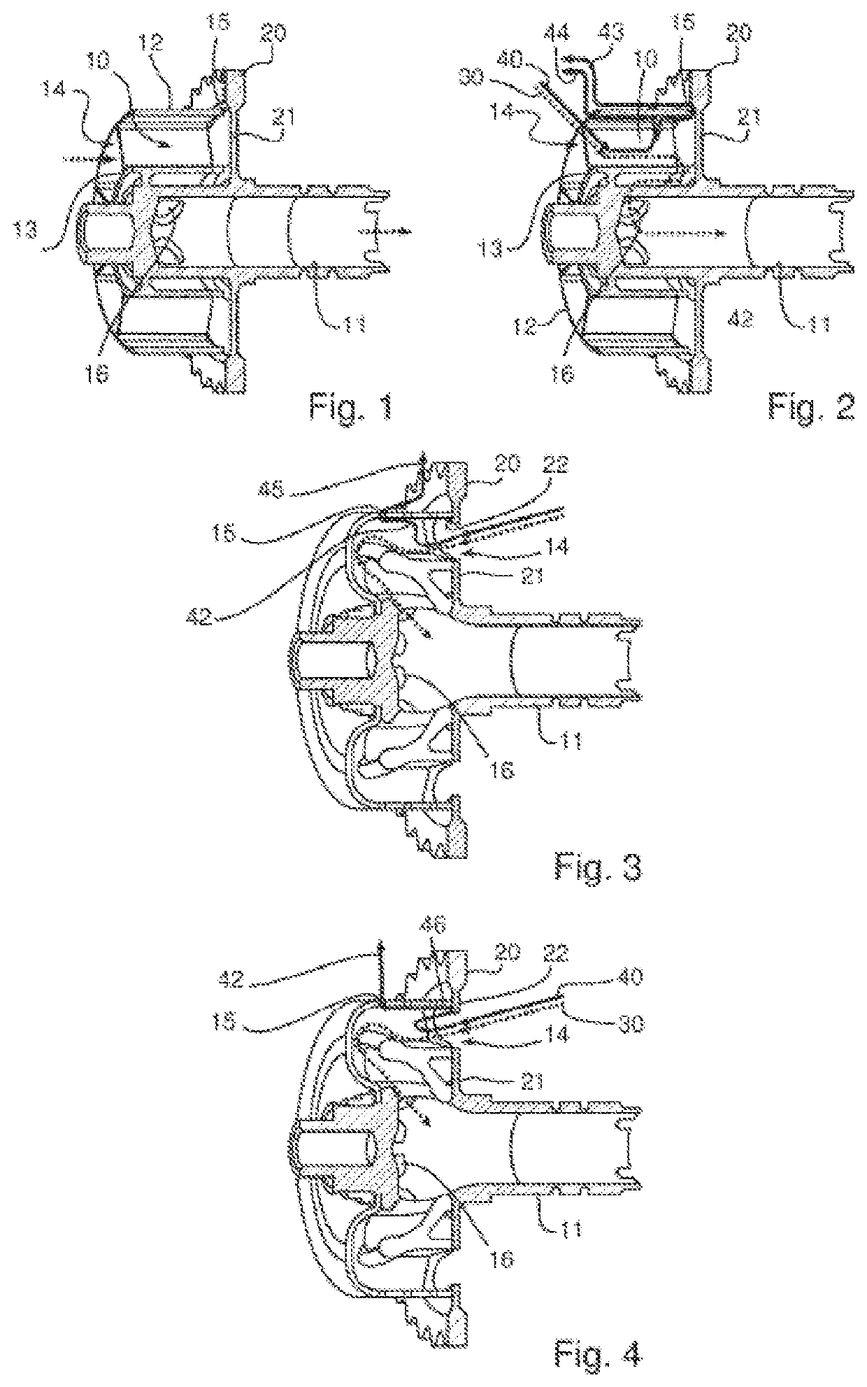
The inventors have realised that in known deaerators, some of the oil extracted through the peripheral outlet of the deaerator is suctioned again through the axial inlet of the deaerator, which limits the performances of the deaerator.
The inventors have also realised that the oil separated from the air by the deaerator forms an oil film which can, in certain cases, be evacuated through the axial air inlet, rather than through the peripheral oil outlet, which contributes to further enriching the air to be de-oiled, and therefore also limits the performances of the deaerator.

Method used


Image

  • Centrifugal deaerator for a turbomachine
  • Centrifugal deaerator for a turbomachine

Examples


Embodiment Construction

[0048]In the figures, the scales and proportions are not strictly adhered to and this, for purposes of illustration and clarity.

[0049]In all the figures and from one embodiment to another, the same number references are used for identical elements, or elements of the same nature.

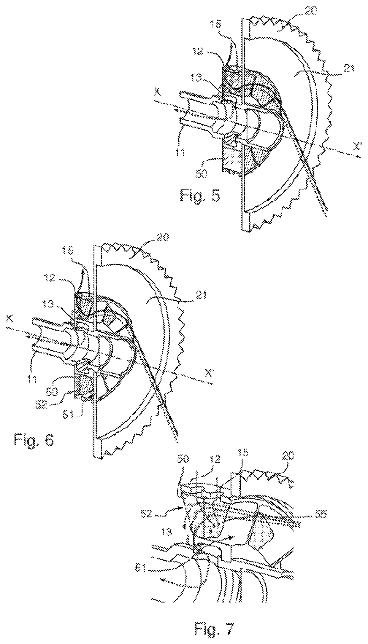
[0050]FIG. 1 illustrates the architecture of a known deaerator. Such a deaerator conventionally comprises an annular enclosure 10 for the centrifugal separation of an air / oil mixture around a hollow shaft 11. This annular enclosure 10 is delimited by an outer annular wall 12 and an inner annular wall 13. This enclosure 10 comprises a plurality of deaerating compartments distributed around the hollow shaft 11.

[0051]The deaerator further comprises a plurality of axial inlets 14 making it possible for the air / oil mixture to enter into the enclosure 10. Generally, and such as represented in the figures, each compartment of the enclosure 10 is connected to an axial inlet 14 such that each compartment can receive ...


PUM


Abstract

A centrifugal deaerator for an air / oil mixture of a turbine engine includes: an annular housing arranged around a hollow shaft and having an outer annular wall and an inner annular wall; axial mixture inlets for the inflow of the air / oil mixture into annular housing; a pinion for rotating the annular housing, the pinion including a web that is securely connected to the hollow shaft and to the inner and outer annular walls; radial oil outlets in the outer wall; and oil-free air outlets in the inner wall. The axial mixture inlets and the radial oil outlets are axially arranged on either said of the web to prevent the axial mixture inlets from reintroducing oil evacuated by radial oil outlets into the enclosure annular housing.

Description

TECHNICAL FIELD OF THE INVENTION[0001]The invention relates to a centrifugal deaerator for a turbine engine.TECHNOLOGICAL BACKGROUND[0002]Turbine engines are complex systems which implement a certain number of rotating units (turbines, compressor, etc.) which must be equipped with sealing devices. These sealing devices are generally produced by pressurized air labyrinths arranged in the vicinity of the rotating units. To do this, air is removed directly in the air duct of the turbine engine. This air then travels into the turbine engine by the different labyrinths provided for this purpose, then is evacuated towards the outside of the turbine engine to limit the increase in pressure of the other zones of the turbine engine, in particular the reduction gear, the accessory box, etc. However, this air having travelled through different zones of the turbine engine, is loaded with oil used for the cooling and lubrication of bearings and pinions of the rotating units. To avoid the oil-loa...

Claims


Application Information

Patent Timeline
IPC IPC(8): F02C7/06F01D25/18
CPCF02C7/32F02C7/06F01D25/18F05D2260/609B01D45/14F01M13/04F01M2013/0422Y02T50/60
Inventor FULLERINGER, BENJAMINPAJARD, JEAN-PIERRECAZAUX, YANNICK
Owner SAFRAN HELICOPTER ENGINES
Learn More