

Gas Turbine Combustor
- Summary
- Abstract
- Description
- Claims
- Application Information
AI Technical Summary
Benefits of technology
Problems solved by technology
Method used
Image

Examples
first embodiment
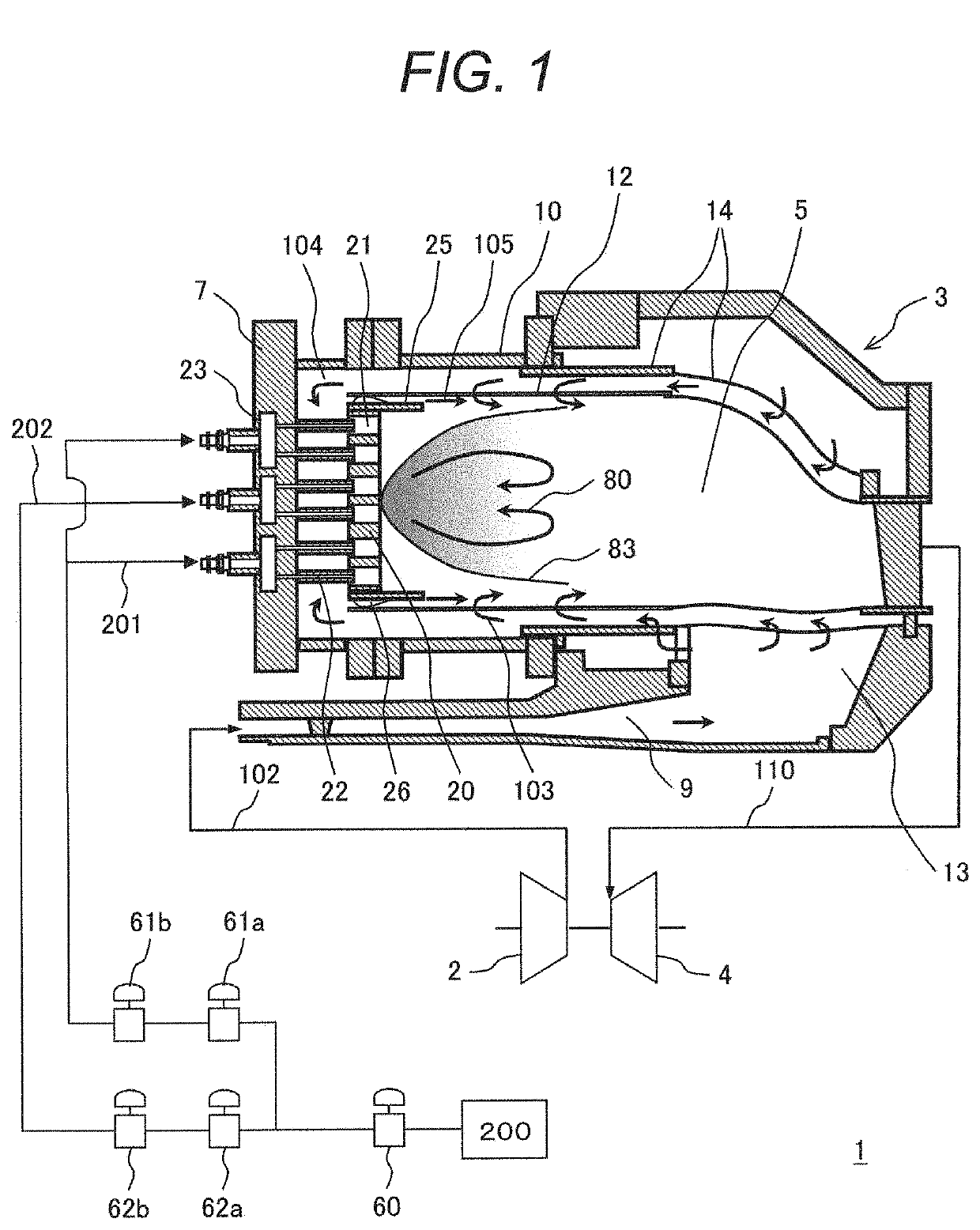
[0026]FIG. 1 is a whole configuration diagram illustrating a structure of a gas turbine combustor in a first example of the present invention.
[0027]In a gas turbine plant 1, compressed air 102 which is compressed by an air compressor 2 passes through a diffuser 9 and flows into a turbine casing 13. The compressed air 102 which flows into the turbine casing 13 passes through a flow sleeve of liner 14 and flows into between an outer casing 10 and a combustion liner 12. Some of the compressed air 102 flows into a combustion chamber 5 as cooling air 103 for the combustion liner 12.
[0028]The compressed air 102 which passes between the outer casing 10 and the combustion liner 12 passes through a spring seal 26 and is distributed to lip cooling air 105 which flows on the outer circumferential side of a plate lip 25 and combustion air 104 which flows into air holes 21 which are installed in an air hole plate 20 and spouts to the combustion chamber 5.
[0029]The combustion air 104 is mixed wit...
second embodiment
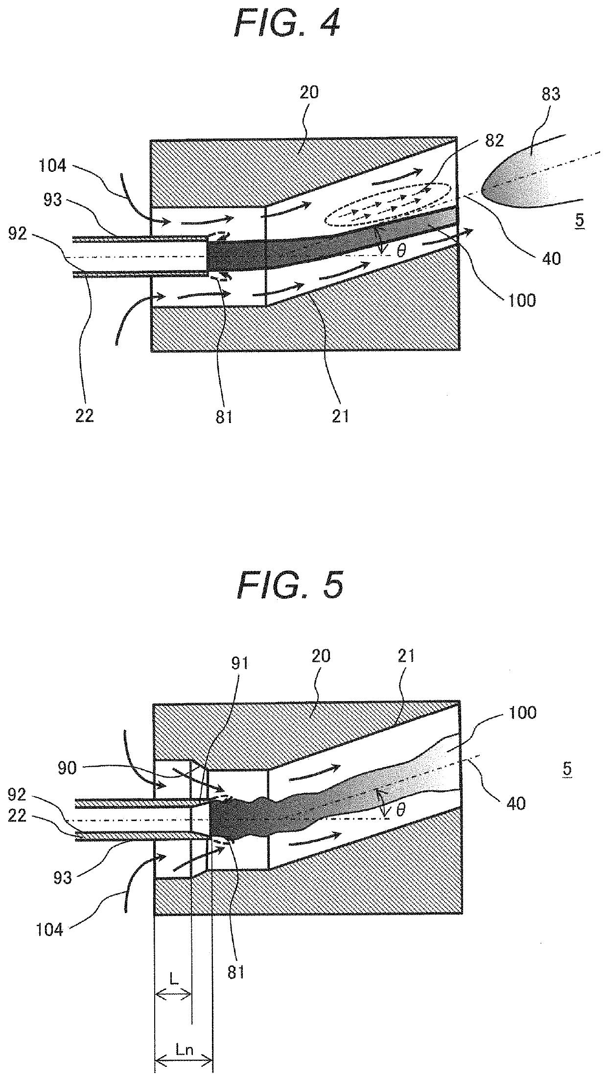
[0058]FIG. 5 is a sectional diagram of one air hole in a second example of the present invention and an enlarged diagram of the air hole plate 20.
[0059]The example illustrated in FIG. 5 is different in that the air hole tapered shape 90 is installed apart from the inlet part of the air hole 21 by a predetermined distance (a distance L) in comparison with the example illustrated in FIG. 3.
[0060]The air hole tapered shape 90 in the present example is installed at an installation position of the leading end part of the fuel nozzle 22 and thereby the combustion air 104 which flows into the air hole 21 can be accelerated on the leading end part of the fuel nozzle 22, a flow of the combustion air 104 can be made to go toward the fuel nozzle 22 and the flow of the combustion air 104 can be changed in addition to the operational effects which are the same as those of Example 1. The flow of the combustion air 104 which goes toward the fuel nozzle 22 acts on the wake flow 81 which is formed o...
third embodiment
[0062]FIG. 6 is a sectional diagram of one air hole in a third example of the present invention and is an enlarged diagram of the air hole plate 20.
[0063]The example illustrated in FIG. 6 is different in that the fuel nozzle tapered shapes 91 are formed on both of the fuel nozzle inner wall 92 and the fuel nozzle outer wall 93 on the leading end part of the fuel nozzle 22 in comparison with the example illustrated in FIG. 5.
[0064]That is, the fuel nozzle inner wall 92 of the leading end part of the fuel nozzle 22 has the fuel nozzle tapered shape 91 which directs in the outer circumferential direction and further the fuel nozzle outer wall 93 of the leading end part of the fuel nozzle 22 has the fuel nozzle tapered shape 91 which directs in an inner circumferential direction. Incidentally, preferably, a leading end part of the fuel nozzle tapered shape 91 has an acute angle shape.
[0065]The fuel nozzle tapered shape 91 is installed also on the fuel nozzle outer wall 93 on the leading...
PUM
 Abstract
Description
Claims
Application Information