System and method for laser marking substrates

Active Publication Date: 2020-03-12
ALLTEC ANGEWANDTE LASER LICHT TECH GMBH
View PDF0 Cites 1 Cited by
  • Summary
  • Abstract
  • Description
  • Claims
  • Application Information

AI Technical Summary

Benefits of technology

[0005]The embodiments encompass the method(s) and system for depositing laser energy in such a manner as to raise the substra

Problems solved by technology

However, there are substrate materials that do not have distinguishable sublayers that allow for ablation of one of the individual layers.
Using a standard CO2 laser marking system to mark white copier paper will produce an ablated mark that is light brown in color and has poor contrast.
Such marks are generally not acceptable to the user.
Common copier paper will carbonize in the temperature range of 200-250° C. Th

Method used


Image

  • System and method for laser marking substrates
  • System and method for laser marking substrates
  • System and method for laser marking substrates

Examples


Example

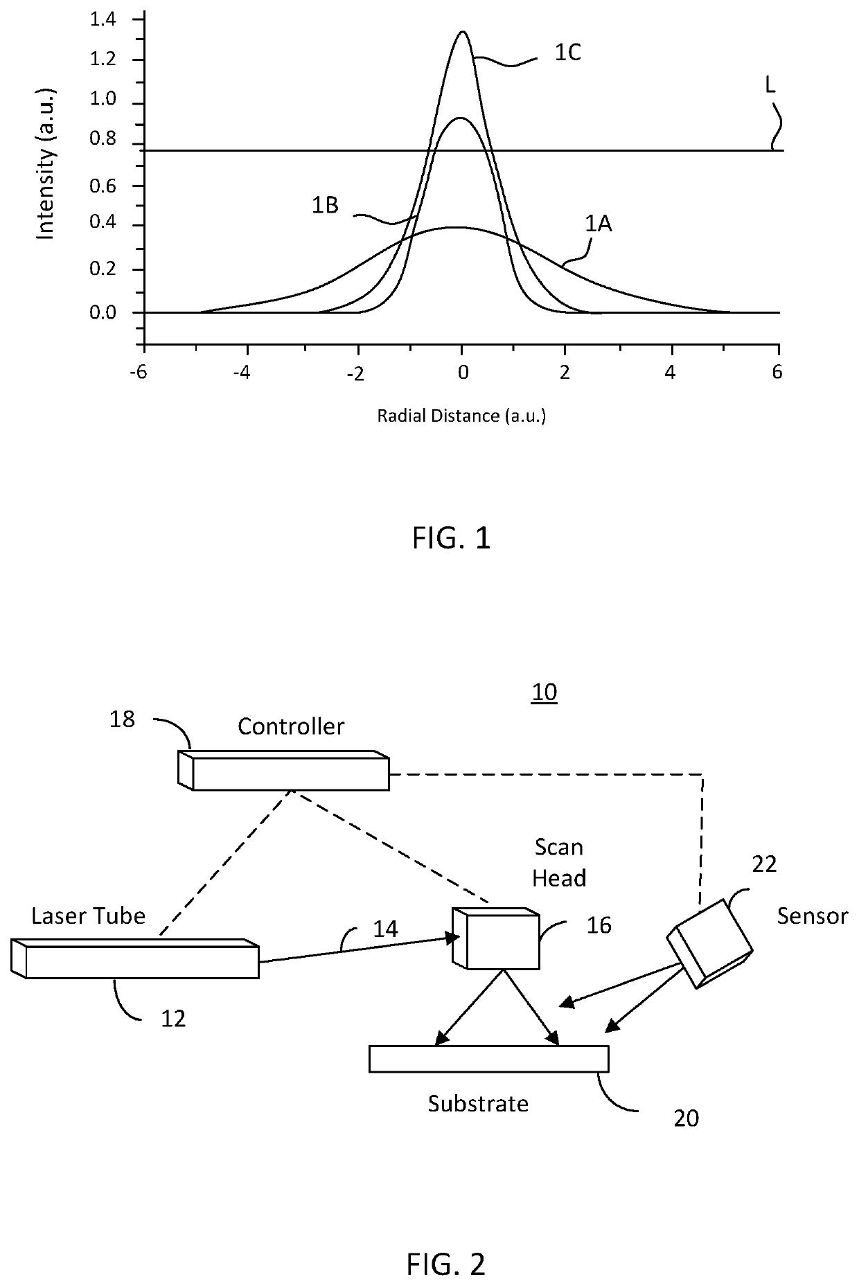
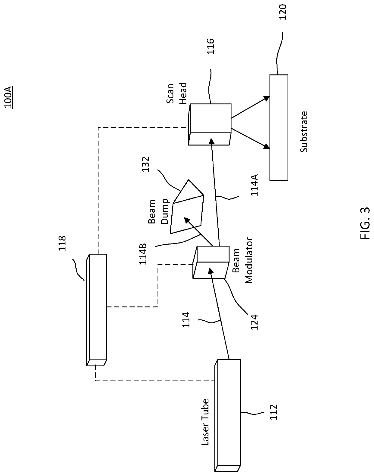
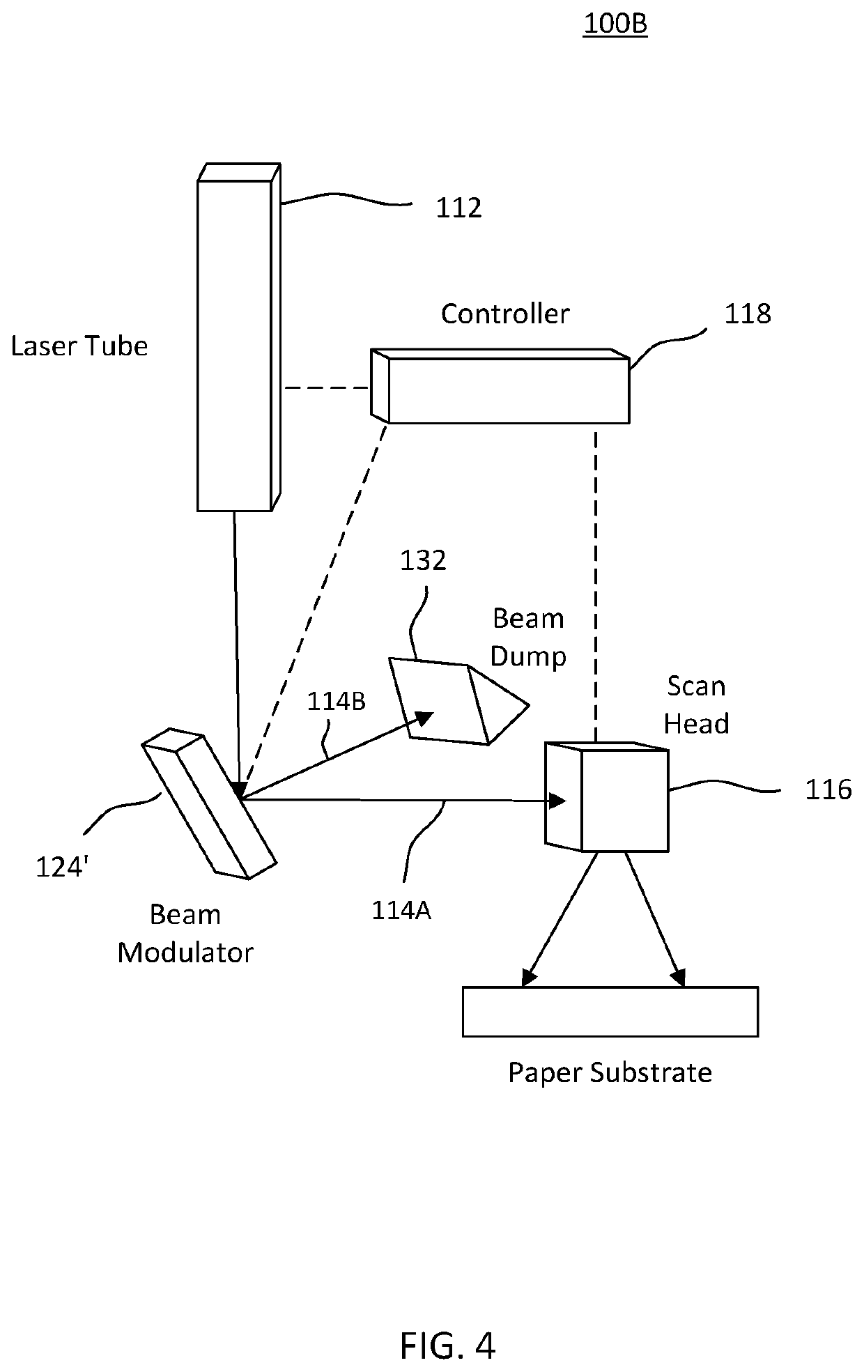
[0033]Embodiments are described herein with reference to the attached figures wherein like reference numerals are used throughout the figures to designate similar or equivalent elements. The figures are not drawn to scale and they are provided merely to illustrate aspects disclosed herein. Several disclosed aspects are described below with reference to non-limiting example applications for illustration. It should be understood that numerous specific details, relationships, and methods are set forth to provide a full understanding of the embodiments disclosed herein. One having ordinary skill in the relevant art, however, will readily recognize that the disclosed embodiments can be practiced without one or more of the specific details or with other methods. In other instances, well-known structures or operations are not shown in detail to avoid obscuring aspects disclosed herein. The embodiments are not limited by the illustrated ordering of acts or events, as some acts may occur in ...


PUM


Abstract

A laser marking system comprises at least one controller to control an array of optical devices, between a laser source and a scan head. The array applies a selected pattern of portions of the received spatial profile of the laser beam to the substrate to achieve a second intensity different from the first intensity of laser beam at a rate of power deposition relative to a rate of thermal diffusion in the substrate for a predetermined time interval to thermally heat locations of the substrate with the selected pattern of the portions. The second intensity effectuates carbonization of materials of the substrate to create a mark without ablation.

Description

BACKGROUND OF THE INVENTION[0001]Embodiments herein relate to generally laser marking systems and methods and more particularly to such systems and methods that are used to mark paper substrates.[0002]The marking of paper based products and packaging is typically accomplished by ablating a layer of material, i.e. ink, to expose an underlying layer of a different color thereby providing contrast. This process does not require finesse by the operator. One only needs to make sure there is sufficient laser energy to remove the top layer and not too much energy to keep from burning through the subsequent layers. Thus, the operator determines the threshold power or energy needed for ablation and ensures that the laser printer operates above that threshold.[0003]However, there are substrate materials that do not have distinguishable sublayers that allow for ablation of one of the individual layers. In these cases, marking is accomplished by a color change that is induced by a chemical reac...

Claims


Application Information

Patent Timeline
IPC IPC(8): B41J2/47B41J2/455B41J2/44
CPCB41J2/442B41J2/47B41J2/455B41M5/26B41J2/435B41J2/44B41J2/4753B41M5/24
Inventor KUECKENDAHL, PETER J.RYAN, DANIEL J.
Owner ALLTEC ANGEWANDTE LASER LICHT TECH GMBH
Why Eureka
Try Eureka