
Method for realizing CHIRP ultra-broadband signal demodulation based on SRAM (Static Random Access Memory) cyclic multiplexing

An ultra-wideband signal and cyclic multiplexing technology, which is applied to electrical components, transmission systems, etc., to achieve the effects of scientific design, minimized area, and high production efficiency

Active Publication Date: 2018-01-05
WUXI ZETAI MICROELECTRONICS
View PDF5 Cites 7 Cited by
  • Summary
  • Abstract
  • Description
  • Claims
  • Application Information

AI Technical Summary

Problems solved by technology

However, according to the definition of CHIRP matched filter, if a higher receiving sensitivity is to be achieved, CHIRP signal demodulation requires a large number of storage units to store historical data and filter coefficients

Method used


Image

  • Method for realizing CHIRP ultra-broadband signal demodulation based on SRAM (Static Random Access Memory) cyclic multiplexing
  • Method for realizing CHIRP ultra-broadband signal demodulation based on SRAM (Static Random Access Memory) cyclic multiplexing
  • Method for realizing CHIRP ultra-broadband signal demodulation based on SRAM (Static Random Access Memory) cyclic multiplexing

Examples


Embodiment Construction

[0014] The technical solutions of the present invention will be described in further detail below through specific implementation methods.

[0015] The expression of the chirp signal, that is, the CHIRP signal is:

[0016]

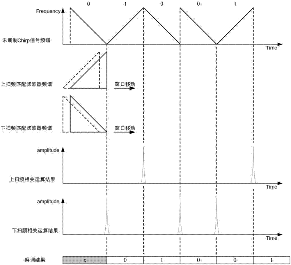
[0017] where μ is the sweep rate, ω 0 is the center frequency, and T is the sweep time. Suppose the frequency bandwidth swept by the CHIRP signal is B, then 2πB=μT. ±μ determines the frequency sweep direction, that is, the change trend of the instantaneous frequency of the signal. When the positive sign is taken, it is Up-CHIRP, and when it is negative, it is Down-CHIRP. The corresponding matched filter The unit impulse response of is:

[0018]

[0019] Where k is the gain of the matched filter, it can be seen that the up-sweep and down-sweep signals are phase conjugate matched to each other.

[0020] The output of the CHIRP signal after passing through the matched filter is:

[0021]

[0022] For the case of t≥0

[0023]

[0024] The sec...


PUM


Abstract

The invention provides a method for realizing CHIRP ultra-broadband signal demodulation based on SRAM (Static Random-Access Memory) cyclic multiplexing. Sampling point data of symbols are saved through an SRAM memory stack; a matched filter coefficient is extracted from 1 symbol, and stored in a 512*16bit SRAM; each symbol rate clock samples one sampling point datum; 16 sampling point data are cached every time; meanwhile, 16 adjacent sampling point data in an RAM (Random Access Memory)) are read out; the 16 adjacent sampling point data can construct a matrix of 16*16 sampling point data, andthe matrix is subjected to a multiplying-accumulating operation with corresponding matched filter coefficients respectively to obtain 16 offset accumulated values of the 16 sampling point data; a system clock and the symbol rate clocks are designed to realize reasonable utilization of each system clock period; an RAM space and a time sequence can be fully utilized through SRAM cyclic multiplexing,so that area minimization is realized, and a demodulating result can be output in real time. The method has the advantages of scientific design, high practicability, small implementation area, and capability of outputting the demodulating result in real time.

Description

technical field [0001] The invention relates to the spread spectrum technology in the field of wireless communication, in particular to a method for realizing CHIRP ultra-wideband signal demodulation based on SRAM cyclic multiplexing. Background technique [0002] Ultra-wideband technology has become a hot spot in wireless communication in recent years. Compared with traditional wireless communication systems, ultra-wideband systems based on CHIRP spread spectrum technology have the advantages of strong anti-interference ability, strong anti-multipath ability, low transmission power, and strong information confidentiality. However, according to the definition of the CHIRP matched filter, if a higher receiving sensitivity is to be achieved, CHIRP signal demodulation requires a large number of storage units to store historical data and filter coefficients. [0003] In order to solve the above existing problems, people have been seeking an ideal technical solution. Contents o...

Claims


Application Information

Patent Timeline
IPC IPC(8): H04B1/7163H04B1/7176H04B1/717
Inventor 张祖兴
Owner WUXI ZETAI MICROELECTRONICS
Learn More