Insulation of a heating mat of a wind turbine blade

a technology of wind turbine blade and heating mat, which is applied in the direction of ohmic-resistance heating, mechanical equipment, machines/engines, etc., can solve the problems of reducing the aerodynamic efficiency of the rotor blade and, hence, the wind turbine, and the rotor blade which is partially or completely covered with ice, etc., and affecting the aerodynamic efficiency

Active Publication Date: 2020-03-12
SIEMENS GAMESA RENEWABLE ENERGY AS
View PDF0 Cites 6 Cited by
  • Summary
  • Abstract
  • Description
  • Claims
  • Application Information

AI Technical Summary

Problems solved by technology

A rotor blade which is partially or entirely covered with ice is generally undesired by the wind turbine operator for various reasons.
First, the aerodynamic efficiency of the rotor blades and, hence, of the wind turbine may be reduced due to the icing.
This is due to the fact that the shape and geometry of the rotor blade is carefully optimized and any deviation of the shape, e.g. by an additional layer of ice or by irregularities of the surface, generally impairs the aerodynamic efficiency.
Second, a layer of ice on the surface of the rotor blade adds weight to the rotor blade, which, if unevenly distributed over the rotor of the wind turbine, may create imbalances of the rotor.
Third, parts of the ice may be thrown from the rotor blades d

Method used


Image

  • Insulation of a heating mat of a wind turbine blade
  • Insulation of a heating mat of a wind turbine blade
  • Insulation of a heating mat of a wind turbine blade

Examples


Embodiment Construction

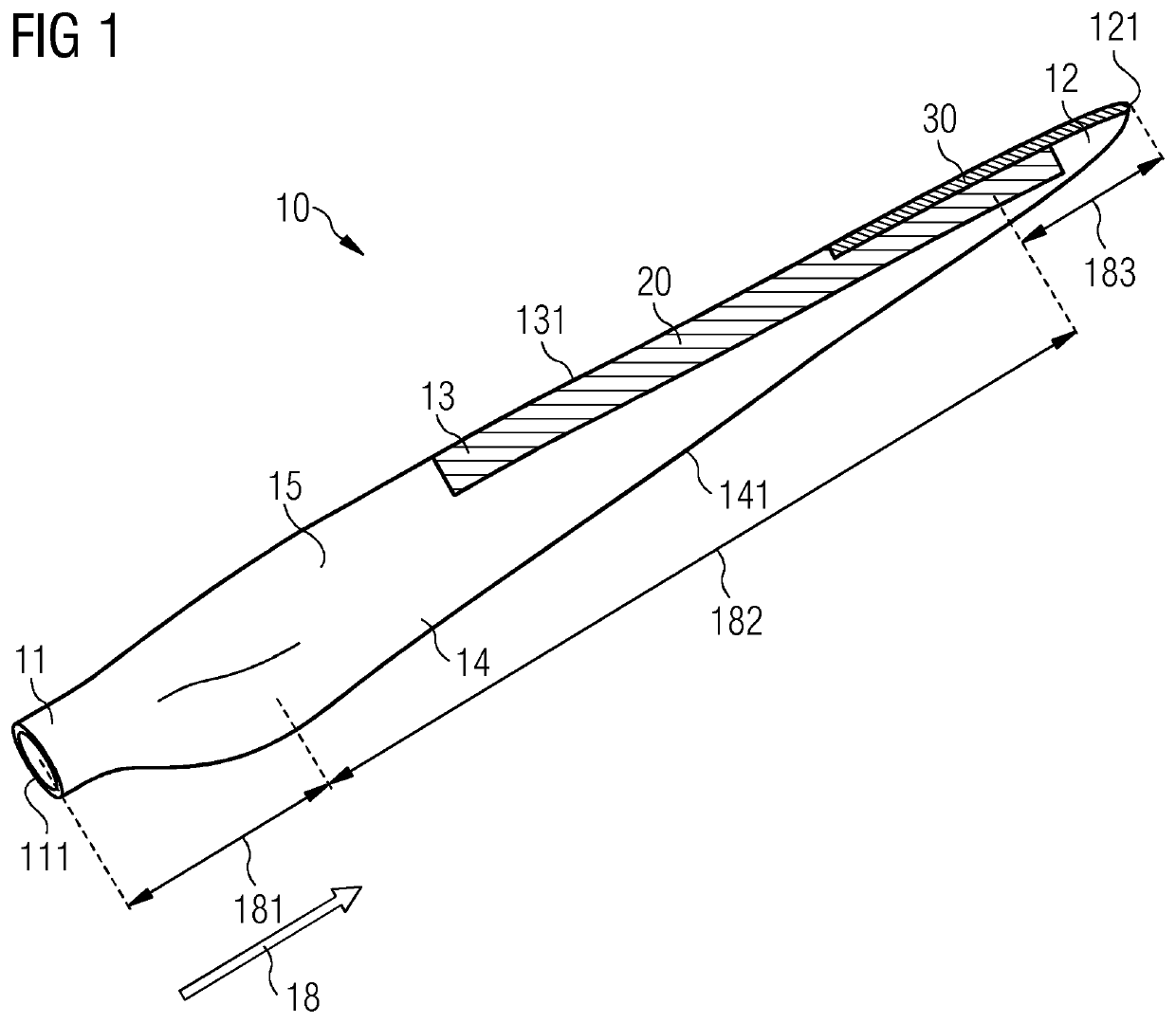
[0045]FIG. 1 shows a perspective view of a known rotor blade 10 of a wind turbine. The rotor blade 10 comprises a root section 11 with a root 111 and, at its opposite end, a tip section 12 with a tip 121. The spanwise direction 18 of the rotor blade 10 is defined as the direction of a straight line extending from the root 111 to the tip 121 of the rotor blade 10. The rotor blade 10 further comprises a leading-edge section 13 with a leading edge 131 and a trailing edge section 14 with a trailing edge 141. The leading edge 131 and the trailing edge 141 divide the surface of the rotor blade 10 into a suction side 15 and a pressure side 16. FIG. 1 shows a view onto the suction side 15 of the rotor blade 10.

[0046]The trailing edge section 14 is defined as that section which is adjacent to the trailing edge 141 and extends until ten percent in chordwise direction. Likewise, the leading-edge section 13 extends until ten percent in chordwise extension away from the leading edge 131.

[0047]Th...


PUM


Abstract

Provided is a rotor blade of a wind turbine including a leading edge section with a leading edge and a trailing edge section with a trailing edge, wherein the leading edge and the trailing edge divide the surface of the rotor blade into a suction side and a pressure side. The rotor blade further includes a blade shell for defining the outer shape of the rotor blade and a heating mat for anti-icing and/or deicing purposes which is arranged upon the blade shell. In the outboard region of the rotor blade, the heating mat is substantially or completely covered by a protective shield made of an electrically insulating polymer material. Use of a protective shield made of electrically insulating polymer material for electrical insulation of a heating mat in particular, against lightning strikes is also provided.

Description

CROSS-REFERENCE TO RELATED APPLICATIONS[0001]This application claims priority to PCT Application No. PCT / EP2018 / 056163, having a filing date of Mar. 13, 2018, which is based off of DE Application No. 10 2017 209 066.9, having a filing date of May 30, 2017, the entire contents both of which are hereby incorporated by reference.FIELD OF TECHNOLOGY[0002]The following relates to a rotor blade of a wind turbine. In particular, the following relates to the use of a protective shield for electrically insulating a heating mat of a rotor blade of a wind turbine.BACKGROUND[0003]Depending on the weather conditions at a specific wind turbine site, icing of the rotor blades of the wind turbine may occur. A rotor blade which is partially or entirely covered with ice is generally undesired by the wind turbine operator for various reasons. First, the aerodynamic efficiency of the rotor blades and, hence, of the wind turbine may be reduced due to the icing. This is due to the fact that the shape and...

Claims


Application Information

Patent Timeline
IPC IPC(8): F03D80/40F03D80/30F03D1/06H05B3/14H05B3/18
CPCF03D80/30F05B2280/2006F03D1/0675F03D80/40H05B3/145H05B3/18F05B2240/2211F03D80/00Y02E10/72
Inventor CAO VAN TRUONG, YANNICKBAK GRISHAUGE, NIKOLAI
Owner SIEMENS GAMESA RENEWABLE ENERGY AS
Why Eureka
Try Eureka