

Electronic device
a technology of electronic devices and cooling components, applied in the direction of electrical equipment, electrical apparatus, electrical apparatus contruction details, etc., can solve the problem of difficulty in sufficiently cooling the cooling target componen
- Summary
- Abstract
- Description
- Claims
- Application Information
AI Technical Summary
Benefits of technology
Problems solved by technology
Method used
Image

Examples
first example embodiment
[0026]An electronic device 1 according to a first example embodiment of the present invention is described with reference to FIG. 1 to FIG. 4.
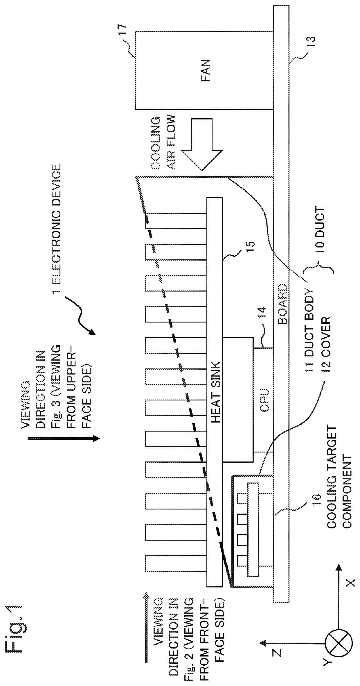
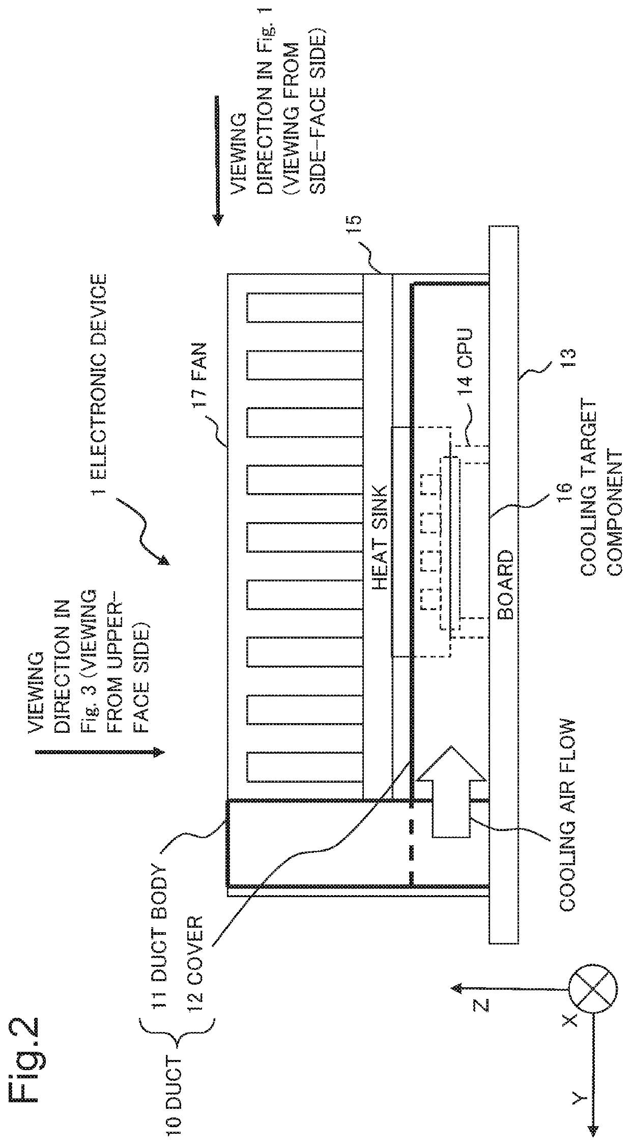
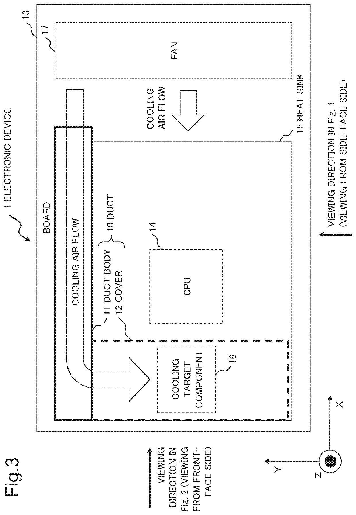
[0027]FIG. 1 is a plan view (XZ plan view) in the case of viewing, from the side-face side, the electronic device 1 according to the present example embodiment. FIG. 2 is a plan view (YZ plan view) in the case of viewing, from the front-face side, the electronic device 1 according to the present example embodiment. FIG. 3 is a plan view (XY plan view) in the case of viewing, from the upper-face side, the electronic device 1 according to the present example embodiment. FIG. 4 is a perspective view of the electronic device 1 according to the present example embodiment. Note that in FIG. 4, for convenience of the description, an illustration of the below-described heat sink 15 is omitted.
[0028]As illustrated in FIG. 1 to FIG. 4, the electronic device 1 according to the present example embodiment includes a duct body 11, a cover 12, a board 13, a ...
second example embodiment
[0053]An electronic device 1A according to a second example embodiment of the present invention is described with reference to FIG. 5 to FIG. 8. In the present example embodiment, regarding the constituents having the functions similar to those in the first example embodiment described above, the same reference symbols as those of the first example embodiment are attached, and thus, the detailed description is omitted.
[0054]FIG. 5 is a plan view (XZ plan view) in the case of viewing, from a side-face side, the electronic device 1A according to the present example embodiment. FIG. 6 is a plan view (YZ plan view) in the case of viewing, from a front-face side, the electronic device 1A according to the present example embodiment. FIG. 7 is a plan view (XY plan view) in the case of viewing, from an upper-face side, the electronic device 1A according to the present example embodiment. FIG. 8 is a perspective view of the electronic device 1A according to the present example embodiment. No...
third example embodiment
[0062]FIG. 9 is a perspective view of an electronic device 2 according to a third example embodiment of the present invention.
[0063]The electronic device 2 according to the present example embodiment includes a duct 20, a board 23, a heat generation component 24, a heat sink 25, and a cooling target component 26.
[0064]The heat generation component 24 is attached to the board 23.
[0065]The heat sink 25 radiates heat generated by the heat generation component 24.
[0066]The cooling target component 26 is between the board 23 and the heat sink 25, and is attached to the board 23.
[0067]The duct 20 is formed in such a way as to take in a part of the cooling air flow for cooling at least the heat sink 25, and to introduce the taken-in cooling air to the cooling target component 26.
[0068]The electronic device 2 according to the present example embodiment is able to sufficiently cool the cooling target component that is between the heat sink increased in size and the board and that is position...
PUM
 Abstract
Description
Claims
Application Information