Doherty amplifier
a technology of amplifiers and amplifiers, applied in amplifiers, amplifier types, amplifiers with semiconductor devices/discharge tubes, etc., can solve problems such as power efficiency degradation, and achieve the effect of high efficiency
- Summary
- Abstract
- Description
- Claims
- Application Information
AI Technical Summary
Benefits of technology
Problems solved by technology
Method used
Image


Examples
first embodiment
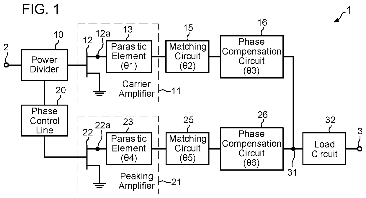
[0018]FIG. 1 is a diagram schematically illustrating a configuration of a Doherty amplifier 1 according to a first embodiment of the present invention. The Doherty amplifier 1 includes: an input terminal 2; a power divider 10 for dividing a high-frequency signal input to the input terminal 2, into two input signals; a carrier amplifier 11 for amplifying power of one input signal (first input signal) output from the power divider 10; a matching circuit (first matching circuit) 15 connected to an output end of the carrier amplifier 11; a phase compensation circuit (first phase compensation circuit) 16 for adjusting the phase of a signal transferred from the output end of the carrier amplifier 11 via the matching circuit 15; a power combiner 31 connected to an output end of the phase compensation circuit 16; a load circuit 32; and an output terminal 3. The matching circuit 15 is a circuit that is located between the output end of the carrier amplifier 11 and an input end of the phase c...
second embodiment
[0040]Next, a second embodiment according to the present invention will be described. FIG. 6 is a diagram illustrating a schematic configuration of a Doherty amplifier 1A according to the second embodiment of the present invention. The Doherty amplifier 1A has the same configuration as that of the
[0041]Doherty amplifier 1 of the first embodiment except that the Doherty amplifier 1A includes a phase compensation circuit 27 having a positive electrical length θ7 as illustrated in FIG. 6 instead of the phase compensation circuit 26 having the negative electrical length θ6 as illustrated in FIG. 1. The phase compensation circuit 27 is a circuit located between an output end of the peaking amplifier 21 and an input end of the phase compensation circuit 26 and performs impedance matching.
[0042]In the present embodiment, similarly to the case of the first embodiment, the phase compensation circuit 16 has a negative electrical length θ3 that allows the total electrical length of a signal tr...
third embodiment
[0045]Next, a third embodiment according to the present invention will be described. FIG. 7 is a diagram illustrating a schematic configuration of a Doherty amplifier 1B according to the third embodiment of the present invention. The Doherty amplifier 1B includes an input terminal 2, a power divider 10, a phase control line 20, a power combiner 31, a load circuit 32, and an output terminal 3, similarly to the first embodiment.
[0046]The Doherty amplifier 1B of the present embodiment includes a carrier amplifier 11B for amplifying power of one input signal (first input signal) output from the power divider 10, a matching circuit (first matching circuit) 17 connected to an output end of the carrier amplifier 11B, a phase compensation circuit (first phase compensation circuit) 18 for adjusting the phase of a signal transferred from the output end of the carrier amplifier 11B via the matching circuit 17, and a phase control line 19 that is located between an output end of the phase compe...
PUM
 Abstract
Description
Claims
Application Information
 - R&D Engineer
- R&D Manager
- IP Professional
- Industry Leading Data Capabilities
- Powerful AI technology
- Patent DNA Extraction
Browse by: Latest US Patents, China's latest patents, Technical Efficacy Thesaurus, Application Domain, Technology Topic.
© 2024 PatSnap. All rights reserved.Legal|Privacy policy|Modern Slavery Act Transparency Statement|Sitemap