Solar drone comprising two aerofoils in tandem to which photovoltaic cells are coupled

a technology of photovoltaic cells and aerofoils, which is applied in the direction of aircrafts, wing shapes, transportation and packaging, etc., can solve the problems of large wingspan, high structural stress, and require the use of composite materials of high-technicity, so as to improve the longitudinal stability of the drone in flight, optimise the aerodynamics of the drone, and reduce the energy needs of flight

Active Publication Date: 2020-03-26
XSUN
View PDF0 Cites 4 Cited by
  • Summary
  • Abstract
  • Description
  • Claims
  • Application Information

AI Technical Summary

Benefits of technology

The drone in this patent has a large surface area that can hold many photovoltaic cells with good flying ability. The position of the cells on the drone's surface is optimized to catch the most sun and reduce energy needs for flight. This also prevents the drone from getting shadowed by its own wings.

Problems solved by technology

However, these solutions induce many disadvantages.
However, known solutions make use of drone architectures that can cause high structural stresses when the drone is in flight.
These structural stresses may be the result of an excessive wingspan and require the use of high technicity composite materials.
The structural stresses of these architectures are then accompanied by a large wingspan and a high manufacturing cost of drones.
Furthermore, known architectures lead to bad placement of photovoltaic cells relative to the structural elements of the drone, consequently reducing the global insolation to which photovoltaic cells coupled on this drone are exposed.
Therefore such architectures are prejudicial to the extent to which photovoltaic cells are exposed to sunshine, even though these same photovoltaic cells add weight to the drone.
Thus, there is a degradation to the performances and endurance of a drone designed with one of these architectures.
This characteristic can result in an elliptical distribution of lift along the wing.
Furthermore, stalling starts at the root, and then the end of the wing.

Method used


Image

  • Solar drone comprising two aerofoils in tandem to which photovoltaic cells are coupled

Examples


Embodiment Construction

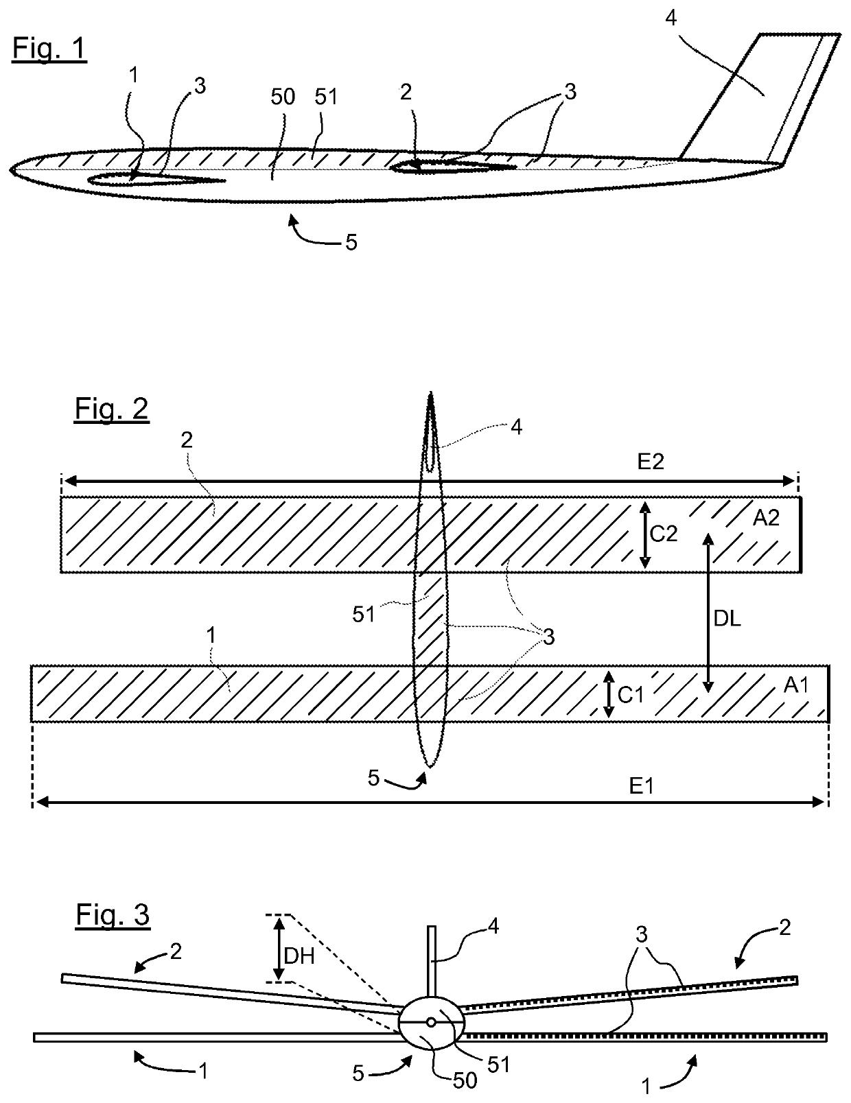
[0054]The drone according to the invention and illustrated in FIGS. 1, 2, and 3 comprises:[0055]a fuselage;[0056]wings composed of two aerofoils arranged in tandem;[0057]a vertical stabiliser 4.

[0058]The drone is provided with propulsion elements (not shown) powered at least by electrical accumulators and / or photovoltaic cells. These propulsion elements may be in the form of one or several electric motors with propellers coupled to the fuselage and / or aerofoils.

[0059]With reference to FIGS. 1 to 3, the drone also comprises photovoltaic cells 3 that essentially cover the top faces of the two aerofoils.

[0060]The drone is thus of the “solar drone” type. The photovoltaic cells 3 enable the drone to supply power to its propulsion elements and recharge its electric accumulators when they are exposed to sunshine.

[0061]More precisely, the drone comprises wings composed of a forward aerofoil 1 and an aft aerofoil 2. These aerofoils are straight wings.

[0062]The expression “composed of” means ...


PUM


Abstract

A flying drone, which includes: a fuselage composed of a single central body; wings composed of a forward aerofoil and an aft aerofoil, the aft aerofoil being offset in height and in length along the fuselage relative to the forward aerofoil; propulsion powered at least by electrical accumulators and / or photovoltaic cells; and photovoltaic cells essentially covering the upper faces of the forward aerofoil and the aft aerofoil.

Description

CROSS-REFERENCE TO RELATED APPLICATIONS[0001]This Application is a Section 371 National Stage Application of International Application No. PCT / FR2017 / 053708, filed Dec. 19, 2017, the content of which is incorporated herein by reference in its entirety, and published as WO 2018 / 115724 on Jun. 28, 2018, not in English.FIELD OF THE DISCLOSURE[0002]The domain of the invention is the design and fabrication of flying drones.[0003]The invention relates most particularly to fixed wing drones powered by photovoltaic cells.BACKGROUND OF THE DISCLOSURE[0004]Fixed wing drones correspond to drones driven by motors, and that comprise wings that provides sufficient lift for the drone to fly, starting from a predetermined drone displacement speed. These “fixed wing” drones are in contrast with “rotating wing” drones for which lift is provided by one or several rotors.[0005]Flying devices of this type may be small or large and propelled by different types of motor drives.[0006]Drones equipped with a...

Claims


Application Information

Patent Timeline
IPC IPC(8): B64D27/24B64C39/02B64C3/10B64C39/08
CPCB64C2201/104B64D2211/00B64D27/24B64C3/10B64C2201/042B64C2201/021B64C39/08B64C39/024B64U10/25B64U50/19B64U30/10B64U50/31B64D27/353
Inventor DAVID, BENJAMIN
Owner XSUN
Why Eureka
Try Eureka