
Electronically controlled valve for a shock absorber

Pending Publication Date: 2020-03-26
OHLINS
View PDF5 Cites 0 Cited by
  • Summary
  • Abstract
  • Description
  • Claims
  • Application Information

AI Technical Summary

Benefits of technology

The valve described in this patent is designed to regulate fluid flow. As the spool moves, fluid is routed into the piston holder, allowing the spool to control fluid flow. By controlling the pressure at the inlets of the piston holder, the pressure inside the valve remains constant, regardless of the pressure in the chamber where the actuator is located. This design helps prevent the shock absorber from fading. Additionally, the valve includes a sealing element that isolates the pressure compensation chamber from the portion of the housing containing the actuator. This ensures that the net force acting on the spool is in the desired direction, and that the valve operates effectively.

Problems solved by technology

A drawback of the valve is that the actuator is slow which makes adjustment of the position of the needle slow.

Method used


Image

  • Electronically controlled valve for a shock absorber
  • Electronically controlled valve for a shock absorber
  • Electronically controlled valve for a shock absorber

Examples


Embodiment Construction

[0039]The disclosed embodiments will hereinafter be described in more detail with reference to the accompanying drawings in which several embodiments of the invention are shown. However, the invention may be embodied in many different forms and should not be construed as limited to the embodiments set forth herein. Rather, these embodiments are provided by way of example so that this disclosure will be thorough and complete, and will fully convey the scope of the invention to those skilled in the art. Like numbers refer to like elements throughout the description.

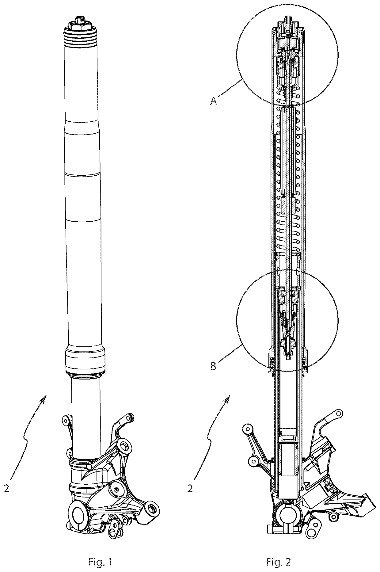
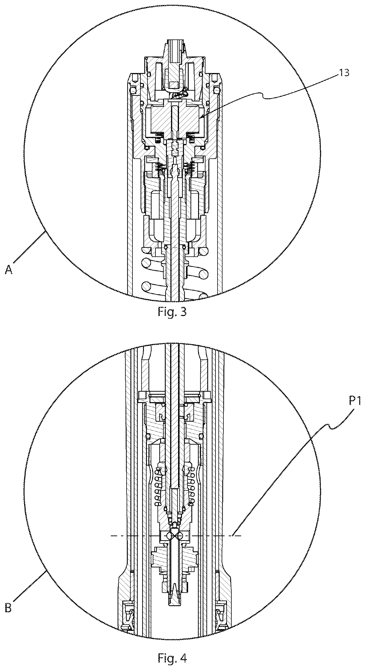
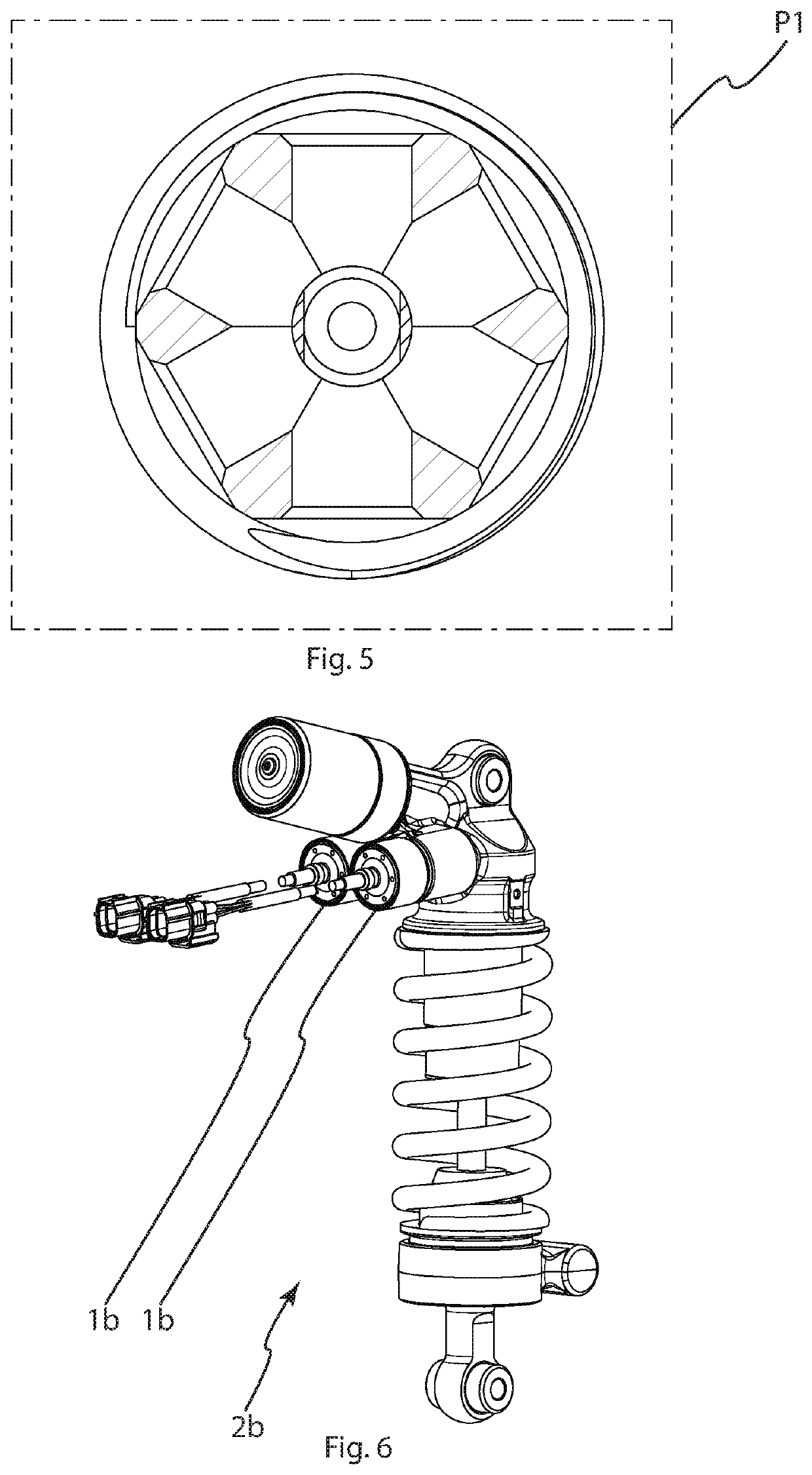
[0040]A shock absorber 2a comprising a valve according to a first embodiment of the invention is shown in FIGS. 1-4 and 6. A valve according to a second embodiment of the invention is shown in FIGS. 5 and 7.

[0041]The shock absorber 2a of FIGS. 1-4 is typically used for damping the movement of a front wheel of a motorcycle, although other uses are possible. The damper uses a known twin tube design to route damping fluid duri...


PUM


Abstract

An electrically controlled valve (1) for a shock absorber (2). The valve comprises a piston (7) providing a primary fluid channel (10) for damping fluid. A piston holder (5) is provided with an internal secondary fluid channel (11) for damping fluid. Fluid flow (23) through the secondary fluid channel is controlled by a spool (12) movable within the piston holder (5) by means of an electrically controlled actuator (13). Fluid flow (23) through the secondary fluid channel (11) is controlled by restriction at the inlet of the secondary fluid channel (11), said inlet comprising one or more radial holes through the piston holder.

Description

CROSS REFERENCE TO THE RELATED APPLICATION[0001]This application is a continuation application, under 35 U.S.C. § 111(a), of international application No. PCT / EP2018 / 064515, filed on Jun. 1, 2018, which claims priority on European Patent Application No. 17174115.0 filed on Jun. 1, 2017, the entire content of both of which are incorporated herein as a part of the application.BACKGROUND[0002]Some modern shock absorbers are provided with electronically controlled valves for dynamically adjusting the damping properties of the shock absorber by adjusting the throughput of the valve.[0003]Some known electrically controllable valves comprise a needle valve controlling fluid flow through the valve. Larger fluid pressures increase forces on the needle, which in turn leads to the need of a stronger actuator to control movement of the needle in order to open or close the valve.[0004]It is generally advantageous to provide small valves for example in order to reduce the size of the dampers and ...

Claims


Application Information

Patent Timeline
IPC IPC(8): F16F9/46F16K31/06F16K11/07
CPCF16F9/469F16K11/0716F16K31/0613F16F9/461F16F9/466
Inventor LINDBLAD, GEIR
Owner OHLINS
Features
  • Generate Ideas
  • Intellectual Property
  • Life Sciences
  • Materials
  • Tech Scout
  • Unparalleled Data Quality
  • Higher Quality Content
  • 60% Fewer Hallucinations
Learn More